Equipment for conveying with revolving suction belts

A suction belt and equipment technology, applied in the directions of sending objects, transportation and packaging, thin material handling, etc., to achieve the effect of maintaining constant friction, offsetting friction, and preventing changes

Inactive Publication Date: 2019-06-14
HEIDELBERGER DRUCKMASCHINEN AG
View PDF8 Cites 0 Cited by
  • Summary
  • Abstract
  • Description
  • Claims
  • Application Information

AI Technical Summary

Problems solved by technology

At another moment when the sheet is transferred from the suction belt to the output of the receiver, the speed fluctuation of the suction belt will be formed due to the sudden decrease in pressure.
This results in a stomp-like (stoβartig) movement of the sheet just below the printhead and, in conveyor belt-based digital printing presses, may result in visible streaks on the printed image

Method used


Image

  • Equipment for conveying with revolving suction belts
  • Equipment for conveying with revolving suction belts
  • Equipment for conveying with revolving suction belts

Examples


Embodiment Construction

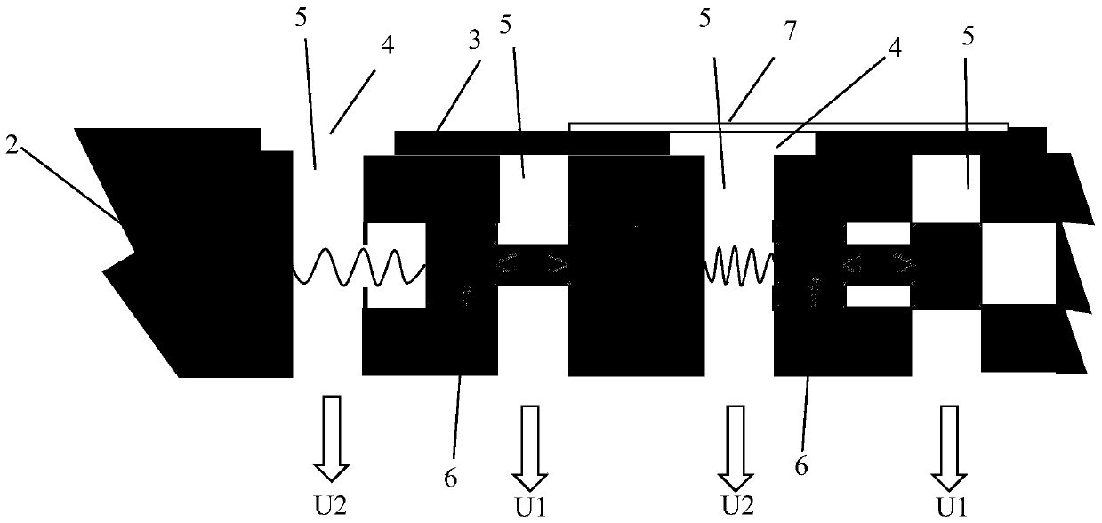
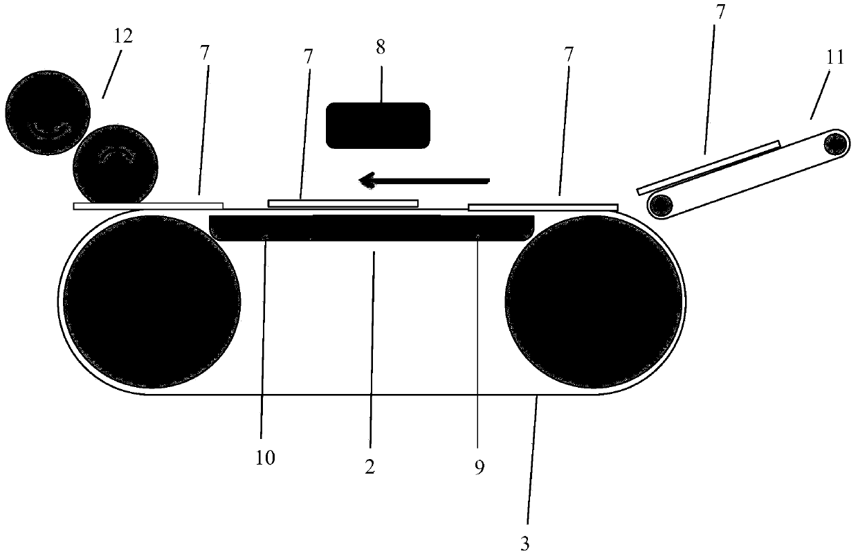
[0021] The sheets 7 are received in the feeder 11 and fed to the suction belt 3 . There, the sheet 7 is sucked through the suction opening 4 of the suction belt by the suction opening 5 of the suction box, and the sheet 7 is taken up by the revolving suction belt 3 . In this case, the first suction opening 5 is initially covered by the sheet 7 . In this case, the negative pressure U2 acts on the sheet 7 . Below the suction opening 5 covered by the suction belt 3 a negative pressure acts with a value U1. When the suction opening 5 of the suction box, which is not covered by the sheet 7 , is passed by the suction opening 4 of the suction belt, no underpressure is formed.

[0022] Below the suction opening 5 covered by the sheet 7 a negative pressure U2 builds up. This negative pressure tensions the spring-loaded switching element 6 and thus switches off the negative pressure U1 in the region of the suctioned sheet 7 .

[0023] In addition, the switching element 6 on the side...


PUM


Abstract

The invention relates to a device for transporting sheet-like substrates with a circumferential suction belt and a suction box below. The device is characterized in that, at least in a part of the suction box, additional and switchable suction openings are present, by means of which the suction belt itself can be sucked.

Description

technical field [0001] The invention is used in sheet printing presses by means of a revolving suction belt. Background technique [0002] The moment the sheets are transferred from the feeder to the suction belt, there is a sudden negative pressure. This negative pressure presses the suction belt against the suction box, which leads to increased friction between the two aforementioned parts (suction belt and suction box). The resulting change in the drive torque has an effect in the form of fluctuations in the delivery speed. And when the sheet is delivered from the suction belt to another moment of output on the receiver, this speed fluctuation of the suction belt will be formed due to the sudden reduction of pressure. This leads to a stomp-like (stoβartig) movement of the sheet directly below the printing head and, in conveyor belt-based digital printing machines, can lead to visible streaks on the printed image. [0003] DE 3017420 A1 describes a system in which the t...

Claims


Application Information

Patent Timeline
Patent Type & Authority Patents(China)
IPC IPC(8): B65H5/22B65H29/32
CPCB65H29/242B41J11/007B41J11/0085B65H2406/3124B65H2406/363B65H2801/15B65H2801/21
Inventor D·埃尔巴A·米勒
Owner HEIDELBERGER DRUCKMASCHINEN AG
Why Eureka
Try Eureka