
Surface aerator capable of promoting flow expansion

A surface aerator and water flow dispersion technology, applied in water aeration, biological water/sewage treatment, water/sludge/sewage treatment, etc., can solve flow loss, water flow cannot be smoothly transitioned, and cannot reach the maximum diffusion area, etc. question

Inactive Publication Date: 2016-10-12
川源(中国)机械有限公司
View PDF6 Cites 0 Cited by
  • Summary
  • Abstract
  • Description
  • Claims
  • Application Information

AI Technical Summary

Problems solved by technology

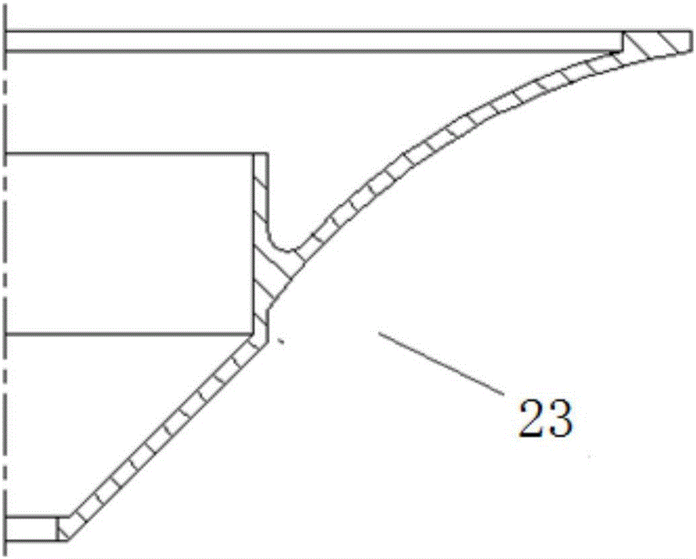
[0002] like figure 2 As shown, the diversion cover of the existing surface aerator has a stepped structure on the flow surface. When the aerator is running, the water flow cannot transition smoothly, the flow is lost, and the maximum diffusion area cannot be reached.

Method used


Image

  • Surface aerator capable of promoting flow expansion
  • Surface aerator capable of promoting flow expansion
  • Surface aerator capable of promoting flow expansion

Examples


Embodiment 1

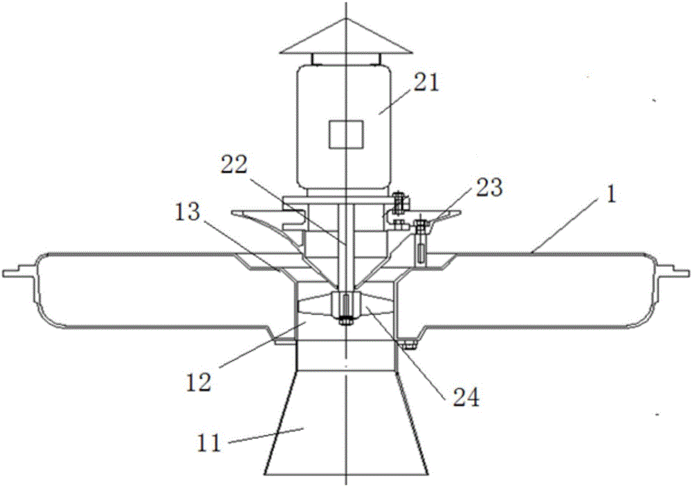
[0021] Example 1, such as figure 1 As shown, a surface aerator includes a buoy 1, a motor 21 installed on the buoy 1, and an axial flow impeller 24. The horizontal center of the buoy is provided with a water absorption channel 12 connected up and down. A water inlet 11 communicated with the water absorption channel 12 is provided, a water outlet 13 communicated with the water absorption channel 12 is provided on the upper part of the buoy, the motor 21 is arranged above the water outlet 13 and vertically arranged, and the output shaft of the motor is placed downward and The pump shaft 22 is connected, and the motor 21 is provided with a shroud 23 surrounding the pump shaft 22. The shroud 23 is set corresponding to the water outlet 13. The bottom of the pump shaft 22 is exposed from the shroud 23 and extends into the water-absorbing The channel 12 is also equipped with the above-mentioned axial flow impeller 24 . In the water suction channel 12, the motor 21 drives the axial ...

Embodiment 2

[0031] Embodiment 2, in order to make the rainproof cover 3 not only play the role of heat dissipation of the motor but also play the role of rainproof. Such as Figure 6 As shown, the present invention is provided with an annular ventilation ring 32 between the rain shield cap 31 and the end cover 25 , and the motor end cover 25 is fixed to the motor body by screws 251 . The ventilation ring 32 has ventilation openings 321 distributed along the circumferential direction, and an annular rain-shielding ring 33 is provided on the inner peripheral side of the ventilation ring. The ventilation ring 32 is used to realize ventilation and heat dissipation of the motor, while the rain-shielding ring 33 can effectively prevent rainwater from intruding into the motor.

[0032] Such as Figure 7 As shown, the ventilation ring 32 is in the shape of a rectangular strip after being unfolded, and the ventilation opening 321 is a rectangular notch provided at the bottom of the ventilation r...


PUM


Abstract

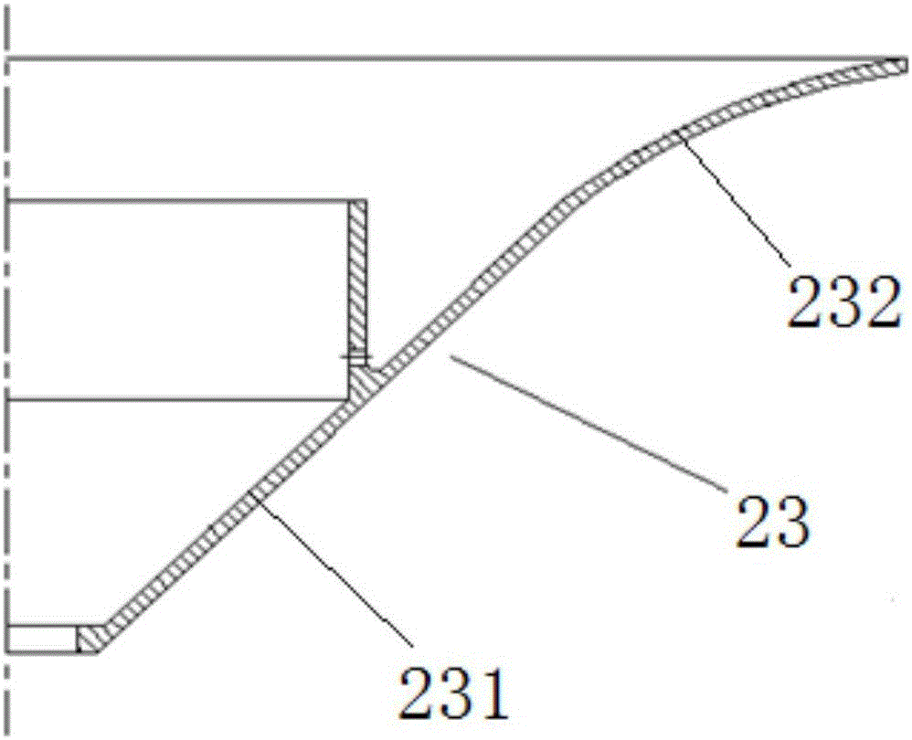
The invention discloses a surface aerator capable of promoting flow expansion. The surface aerator comprises a float, a motor and an axial-flow type impeller, wherein the motor and the axial-flow type impeller are installed on the float. A vertical-through water absorption channel is arranged in the center of the horizontal direction of the float. A water inlet communicated with the water absorption channel is formed below the float. The upper portion of the float is provided with a water outlet communicated with the water absorption channel. The motor is arranged above the water outlet vertically. A pump shaft is connected to an output shaft of the motor. The bottom of the pump shaft stretches into the water absorption channel and is provided with the axial-type impeller. A wind deflector is arranged at the portion, corresponding to the water outlet, below the motor. The wind deflector comprises a bottom back taper section and an upper arc section. An arc transition structure is arranged between the back taper section and the arc section. The surface of the upper half portion of the float is provided with a plurality of flow expansion protrusions achieving the flow impact effect during water outflowing of the surface aerator. According to the surface aerator, the flow loss can be reduced, the flow expansion area can be increased, and the aeration effect is improved.

Description

technical field [0001] The present invention relates to aeration equipment. Background technique [0002] Such as figure 2 As shown, the flow guide cover of the existing surface aerator has a stepped structure on the flow surface. When the aerator is running, the water flow cannot transition smoothly, the flow is lost, and the maximum diffusion area cannot be reached. Contents of the invention [0003] The technical problem to be solved by the present invention is to provide a surface aerator that facilitates water flow diffusion, reduces flow loss, increases water flow diffusion area, and increases aeration effect. [0004] In order to solve the above-mentioned technical problems, the present invention adopts the following technical proposal: a surface aerator that facilitates water flow diffusion, including a buoy, a motor installed on the buoy, and an axial-flow impeller. A connected water absorption channel, the bottom of the buoy is provided with a water inlet conne...

Claims


Application Information

Patent Timeline
Patent Type & Authority Applications(China)
IPC IPC(8): C02F7/00C02F3/02
CPCC02F3/02C02F7/00C02F2203/006Y02W10/10
Inventor 金刚
Owner 川源(中国)机械有限公司
Learn More