

High precision thread trimming device and method for embroidery machine
An embroidery machine, high-precision technology, applied to embroidery machines, embroidery machine mechanisms, textiles and papermaking, etc., can solve problems such as low precision, uncontrolled trimming length, lack of hook knife position trimming length, etc., to achieve high precision The effect of controlling and avoiding the fluctuation of spindle speed
- Summary
- Abstract
- Description
- Claims
- Application Information
AI Technical Summary
Problems solved by technology
Method used
Image

Examples
Embodiment Construction
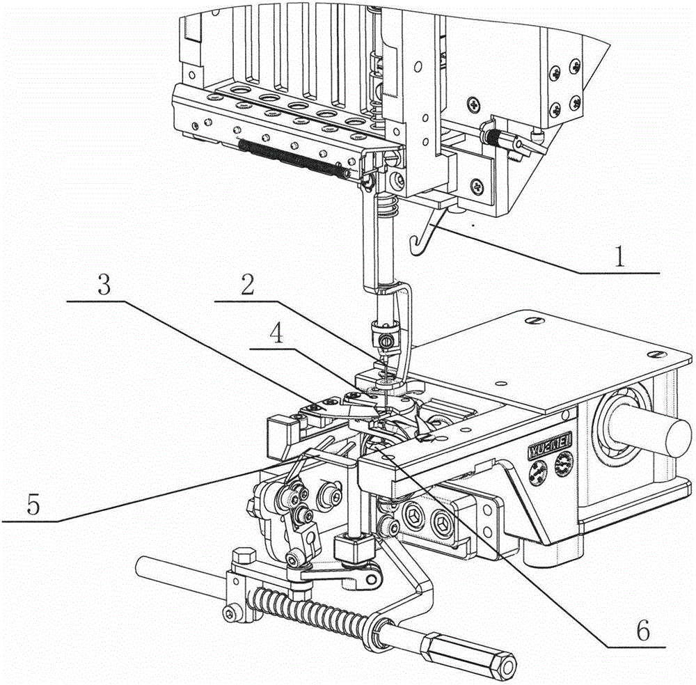
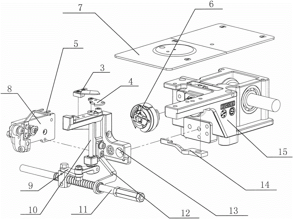
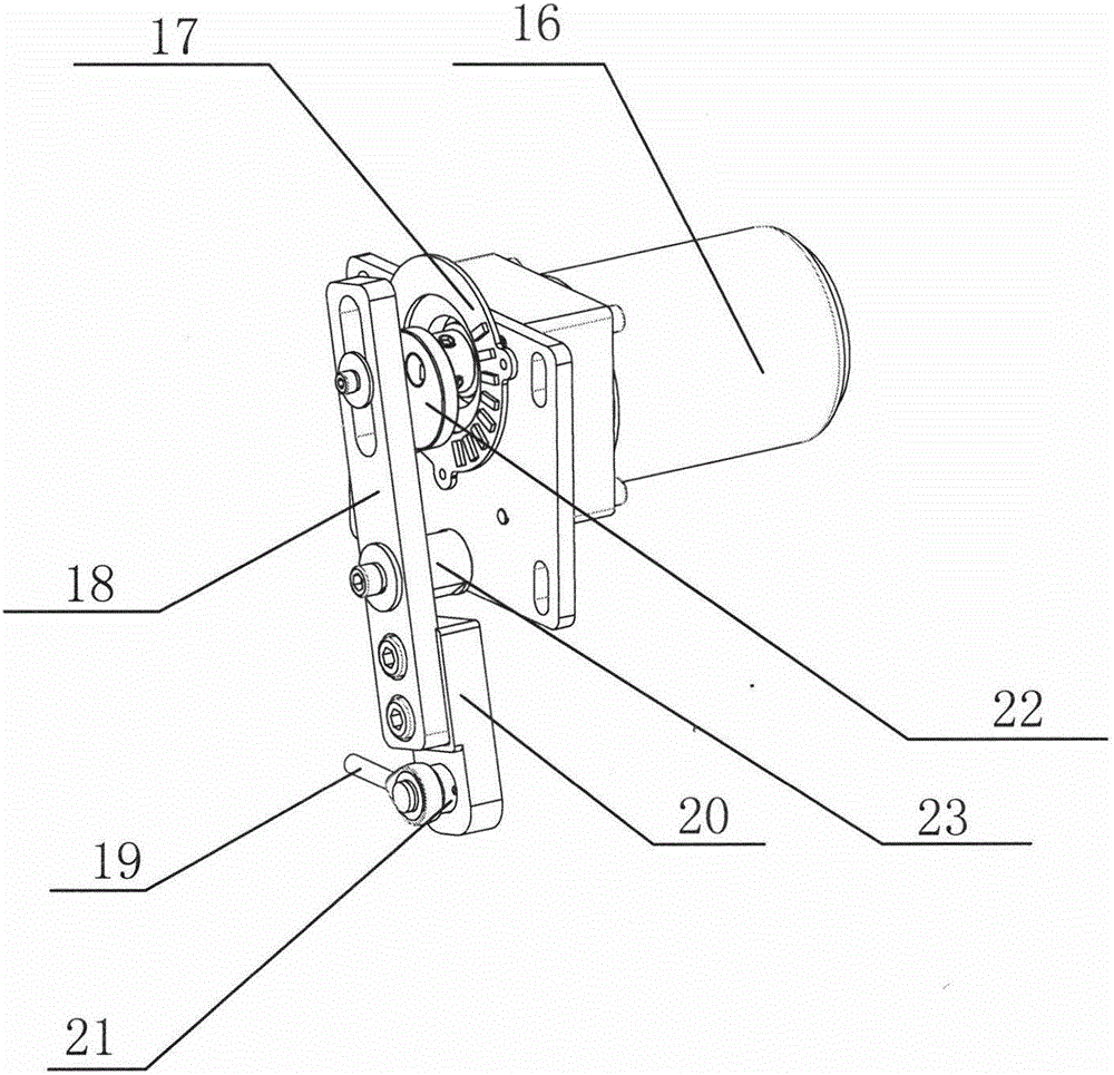
[0017] Such as Figures 1 to 4 A high-precision thread trimming embroidery machine thread trimming device is shown, including a hook knife driving device located on the upper side of the needle plate 7 and a thread trimming device located on the lower side of the needle plate. The hook knife driving device includes a hook knife motor 16, a hook knife A position sensor 17 and an eccentric wheel 22 are arranged on the outer periphery of the drive shaft of the motor 16, and the eccentric wheel 22 is connected to a swing rod 18 with a chute at one end through a roller. The other end is connected to drive the pull bar of hook knife 1 by connecting rod 19 . The hook knife motor 16 is installed on the crossbeam bottom surface of the embroidery machine, and the fork 18 swings horizontally. The preferred technical structure is that the swing rod 18 and the connecting rod 19 are connected by a connecting block 20, the connecting block 20 is provided with front and rear adjustment groov...
PUM
 Abstract
Description
Claims
Application Information