Method for lifting and installing whole bridge arch rib

A technology of overall lifting and arch ribs, which is applied in bridges, bridge construction, erection/assembly of bridges, etc., can solve the problems of poor cable hoisting accuracy, difficult hoisting, and difficult construction, so as to meet the requirements of installation quality and accuracy, reduce The difficulty of welding quality control and the effect of reducing the acquisition of construction land

Active Publication Date: 2016-10-12
SHANGHAI CIVIL ENG GRP FIFTH +1
View PDF6 Cites 17 Cited by
  • Summary
  • Abstract
  • Description
  • Claims
  • Application Information

AI Technical Summary

Problems solved by technology

[0002] At present, the arch ribs of domestic and foreign steel box arch bridges mostly adopt construction techniques such as cable hoisting, floating hoisting, and tower crane hoisting. However, for long-span steel box arch bridges, due to the large Due to the characteristics of heavy weight and large number of segments, construction techniques such as cable hoisting and floating hoisting often have the disadvantages of difficult hoisting, high safety risks, insufficient positioning accuracy, and long construction period, and the construction is difficult and costly. Difficult to meet construction needs
[0003] For example, in specific construction, when the arch rib of a long-span steel box arch bridge is hoisted by cables, the construction is greatly affected by the surrounding environment of the bridge. The construction period is long, and there are high requirements for the selection of steel wire ropes. In addition, the hoisting accuracy of the cables is also poor, making it difficult to meet the high-precision installation requirements
If floating cranes are used to hoist the arch ribs of long-span steel box arch bridges, due to the heavy weight and high height of the arch rib segments, the requirements for floating cranes are high, and the floating cranes in some waters cannot meet the entry conditions, which has great limitations

Method used


Image

  • Method for lifting and installing whole bridge arch rib
  • Method for lifting and installing whole bridge arch rib
  • Method for lifting and installing whole bridge arch rib

Examples


Embodiment Construction

[0042] The present invention will be further described below in conjunction with the accompanying drawings, but the protection scope of the present invention is not limited to the following examples.

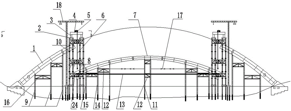
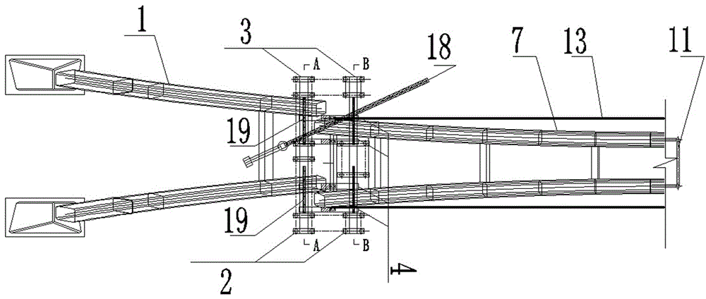
[0043] to combine figure 1 and figure 2 As shown, among them, figure 2 Only the positions of one side arch rib and half of the middle arch rib are shown, and the other half is symmetrically arranged. A method for overall lifting and installation of bridge arch ribs includes the following steps:

[0044] S1. The arch rib is divided into two side arch ribs 1 and a middle arch rib 7, and the two side arch ribs 1 are symmetrically arranged on both sides of the longitudinal central axis of the arch rib; the side arch rib 1 and the middle arch rib 7 According to the design requirements, generally the span of each side arch rib 1 accounts for 20-30% of the entire arch rib span, and correspondingly, the span of the middle arch rib 7 accounts for 60-40% of the entire arch rib;

[00...


PUM


Abstract

The invention discloses a method for lifting and installing a whole bridge arch rib. The method includes the following steps of dividing the arch rib into two side arch rib bodies and a middle arch rib body, splicing the side arch rib bodies on a wharf, hoisting the side arch rib bodies to a set position through a floating hoist, erecting a side supporting system and a lifting portal, installing a lifting system, splicing a middle supporting system below the design position of the middle arch rib body, installing the middle arch rib on the upper face of the middle supporting system, arranging a temporary beam at the bottom of an arch foot of the middle arch rib body, arranging a temporary horizontal rope between the two ends of the arch foot, correspondingly connecting the lifting system with the temporary beam, and lifting, horizontally moving, putting down, putting in position, folding and installing the whole middle arch rib body. By means of the method, the requirements for installation quality and precision of the large-span arch rib bridge can be met, section lengths can be flexibly adjusted, section manufacturing quality is optimized, and section in-situ precision is improved.

Description

technical field [0001] The invention relates to the field of bridge construction, in particular to a method for integrally lifting and installing bridge arch ribs. Background technique [0002] At present, the arch ribs of domestic and foreign steel box arch bridges mostly adopt construction techniques such as cable hoisting, floating hoisting, and tower crane hoisting. However, for long-span steel box arch bridges, due to the large Due to the characteristics of heavy weight and large number of segments, construction techniques such as cable hoisting and floating hoisting often have the disadvantages of difficult hoisting, high safety risks, insufficient positioning accuracy, and long construction period, and the construction is difficult and costly. Difficult to meet construction needs. [0003] For example, in specific construction, when the arch rib of a long-span steel box arch bridge is hoisted by cables, the construction is greatly affected by the surrounding environm...

Claims


Application Information

Patent Timeline
Patent Type & Authority Applications(China)
IPC IPC(8): E01D21/00
CPCE01D21/00
Inventor 唐俊何鹏高剑峰慈俊
Owner SHANGHAI CIVIL ENG GRP FIFTH
Why Eureka
Try Eureka