Ultrahigh flat plate unit lifting mechanism and method utilizing combined locking

A lifting mechanism, flat plate technology, applied in the direction of lifting frame, lifting device, etc., can solve the problem of limited height and space, and achieve the effect of improving the stability of the center of gravity, increasing the load potential, and improving the economy.

Active Publication Date: 2022-08-09
SOUTHWEST CHINA RES INST OF ELECTRONICS EQUIP
View PDF10 Cites 0 Cited by
  • Summary
  • Abstract
  • Description
  • Claims
  • Application Information

AI Technical Summary

Problems solved by technology

[0004] To realize the lifting function of the above-mentioned ultra-high flat panel unit, the main difficulties are as follows: 1) The height space from the bottom d is limited; 2) The space locking of the initial state and the lifting state must be satisfi

Method used


Image

  • Ultrahigh flat plate unit lifting mechanism and method utilizing combined locking
  • Ultrahigh flat plate unit lifting mechanism and method utilizing combined locking
  • Ultrahigh flat plate unit lifting mechanism and method utilizing combined locking

Examples


Embodiment 1

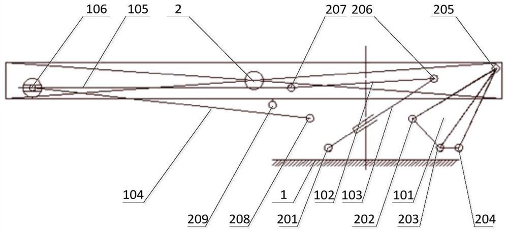
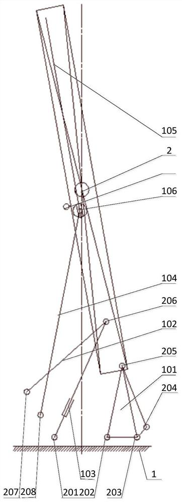
[0047] Embodiment 1: A lifting mechanism for an ultra-high flat panel unit utilizing joint locking, including an active rod 101, a passive rod 102, a locking rod 104, a slide lock 106, a slide rail 105 and a hydraulic cylinder 103, the hydraulic cylinder 103 pushes the super-high flat panel After the unit is raised in place, the active lever 101 completes the locking, and the slide lock 106 located on the slide rail 105 is locked to realize the spatial position locking of the ultra-high flat panel unit; the locking lever 104 is used to provide a stable resistance to the ultra-high flat panel unit. wind moment

Embodiment 2

[0048] Embodiment 2: On the basis of Embodiment 1, the core 2 of the ultra-high flat panel unit is located on the center line of the bottom surface 1.

Embodiment 3

[0049] Embodiment 3: On the basis of Embodiment 1, the active rod 101 is composed of a quadrilateral area formed by connecting the second node 202 , the third node 203 , the fourth node 204 and the fifth node 205 .


PUM


Abstract

The invention discloses an ultrahigh flat plate unit lifting mechanism and method utilizing combined locking, and belongs to the field of transmission mechanisms, the ultrahigh flat plate unit lifting mechanism comprises a driving rod, a driven rod, a locking rod, a sliding lock, a sliding rail and a hydraulic cylinder, after the hydraulic cylinder pushes an ultrahigh flat plate unit to ascend in place, the driving rod completes locking, the sliding lock located on the sliding rail is locked, and the locking rod is locked. Spatial position locking of the ultrahigh flat plate unit is realized; and the locking rod is used for providing stable wind-resistant moment for the ultrahigh flat plate unit. The lifting difficulty of the ultrahigh flat plate unit is solved, the space limitation requirement is met, the strength of the mechanism is improved through the ingenious locking design, and the wind-resistant stability is met.

Description

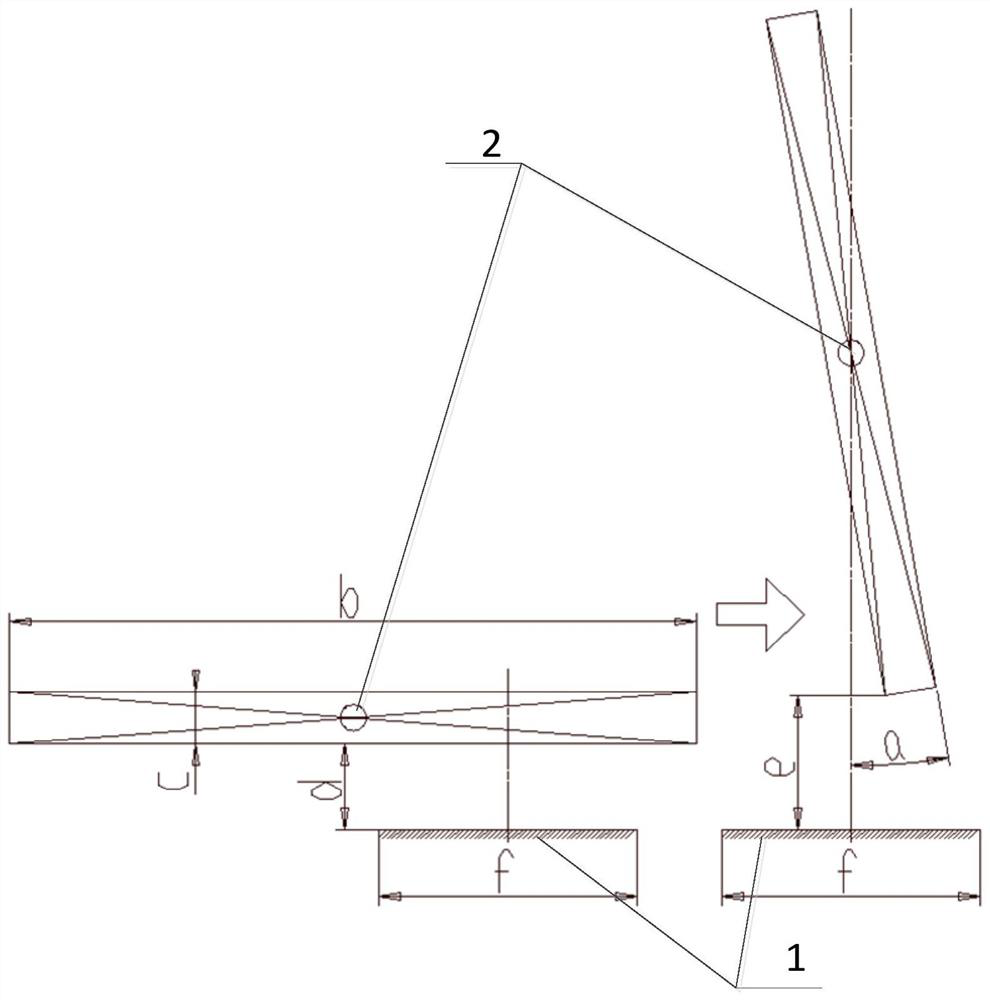
technical field [0001] The invention relates to the field of transmission mechanisms, and more particularly, to a lifting mechanism and a method for an ultra-high flat panel unit utilizing joint locking. Background technique [0002] In the fields of construction machinery, sanitation machinery, amusement equipment, etc., there will be an ultra-high flat panel unit (such as figure 1 shown) to lift to a certain height, and then lock its spatial position and then perform resident work. figure 1 Among them, a is the angle between the ultra-high flat plate unit and the plumb surface, b is the height of the ultra-high flat plate unit, here is 8 meters, c is the thickness of the ultra-high flat plate unit, here is 0.6 meters, and d is the distance between the ultra-high flat plate unit The height of the bottom surface, here is 1 meter, e is the height from the bottom surface after the ultra-high flat panel unit is lifted into place, here is 1.6 meters, f is the width of the botto...

Claims


Application Information

Patent Timeline
IPC IPC(8): B66F7/22B66F7/28B66F7/20
CPCB66F7/22B66F7/28B66F7/20
Inventor 阳丁张永成黄福清杜林秀刘绪第何清明
Owner SOUTHWEST CHINA RES INST OF ELECTRONICS EQUIP
Why Eureka
Try Eureka