Closestool automatic cleaning mechanism

A cleaning mechanism and toilet technology, applied in the field of cleaners, can solve the problems of weakening the decontamination effect, etc., and achieve the effect of good diffusion effect and better cleaning effect

Active Publication Date: 2016-10-12
湖州创星智能科技有限公司
View PDF5 Cites 8 Cited by
  • Summary
  • Abstract
  • Description
  • Claims
  • Application Information

AI Technical Summary

Problems solved by technology

And after using for a period of time, the amount of cleaning agent discharged gradually decreases each time the water is drained, and the concentration of cleaning agent in the discharged aqueous solution is getting lower and lower, so the reciprocation will greatly weaken the decontamination effect

Method used


Image

  • Closestool automatic cleaning mechanism

Examples


Embodiment 1

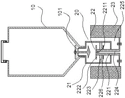
[0020] A toilet automatic cleaning mechanism, as attached figure 1 As shown, it includes a tank body 10 for containing cleaning agent used in conjunction with the toilet, and the tank body 10 is suspended or fixed on the inner wall of the toilet tank. The bottom of the tank body 10 is provided with a diversion port 101, and the diversion port 101 is connected with a control structure 20 for controlling the addition of detergent to the toilet through a one-way valve, including a cylinder body 21 for temporarily storing a small amount of detergent and controlling the The cleaning agent in the cylinder body 21 enters the control body 22 in the toilet. The control body 22 includes a piston tube 221 extending from the bottom of the cylinder body 21 into the inside of the cylinder body 21, a limit plate 222 arranged on the top of the piston tube 221 and a sleeve The piston ring 223 on the outer circumference of the piston tube 221 and the lower baffle plate 226 arranged below the pi...

Embodiment 2

[0022] An automatic toilet cleaning mechanism includes a tank body 10 used in conjunction with the toilet for containing cleaning agents. The bottom of the tank body 10 is provided with a diversion port 101, and the diversion port 101 is connected with a control structure 20 for controlling the addition of detergent to the toilet through a one-way valve, including a cylinder body 21 for temporarily storing a small amount of detergent and controlling the The cleaning agent in the cylinder body 21 enters the control body 22 in the toilet. The control body 22 includes a piston tube 221 extending from the bottom of the cylinder body 21 into the inside of the cylinder body 21, a limit plate 222 arranged on the top of the piston tube 221 and a sleeve The piston ring 223 on the outer circumference of the piston tube 221 and the lower baffle plate 226 arranged below the piston ring 223, the piston tube 221 is provided with a guide channel 224 leading to the bottom of the piston tube 22...


PUM


Abstract

The invention belongs to the technical field of a cleaning device, and particularly relates to a closestool automatic cleaning mechanism. The closestool automatic cleaning mechanism comprises a tank body, wherein the tank body is matched with a closestool to be used and is used for containing cleaning agents; the bottom of the tank body is provided with a flow guide opening; the flow guide opening is connected with a control structure for controlling the cleaning agent from flowing into the closestool through a one-way valve; the control structure comprises a cylinder body for temporarily storing a small number of cleaning agents, a control body for controlling the cleaning agents in the cylinder body to enter the closestool and a gravity time delay body connected with the control body; the gravity time delay body controls the on-off state of the control body. By using the water outlet of the closestool water tank, the fixed amount of cleaning agents are filled; by using the water inlet of the water tank, the fixed amount of cleaning agents are fed into the water tank; new cleaning agents are added for each time of water inlet; along with the slow addition of the water inlet, the diffusion effect of the cleaning agent in the water is good; the concentration of the cleaning agents in a water solution always maintain the consistency; the cleaning effect is better.

Description

technical field [0001] The invention belongs to the technical field of cleaners, in particular to an automatic toilet cleaning mechanism. Background technique [0002] With the improvement of sanitary conditions, flush toilets have been widely popularized in urban and rural areas across the country, which is convenient for the public, but the daily maintenance and cleaning of toilets is relatively cumbersome. Later, flush toilet cleaners with good decontamination effects appeared, such as alum and toilet cleaner. etc., solved the difficult problem of toilet cleaning to a certain extent. But these cleansers in the prior art are mostly by being artificially applied to the dirty place of the toilet, allowing it to decompose for a period of time and then clean it with a toilet brush, which is more loaded down with trivial details. There is also a more convenient toilet block that is put into the water tank to dissolve by itself, but the concentration of the release will be diff...

Claims


Application Information

Patent Timeline
IPC IPC(8): E03D9/03
CPCE03D9/033E03D9/037
Inventor 徐洪飞
Owner 湖州创星智能科技有限公司
Why Eureka
Try Eureka