Combined flow control method and structure for improving SERN for TBCC

A flow control and secondary flow technology, applied in the field of aero-engines, can solve problems such as increasing design costs, increasing engine weight, increasing radar reflection area, etc., and achieves the effects of improving pressure distribution, thrust performance, and thrust coefficient

Inactive Publication Date: 2016-10-12
NORTHWESTERN POLYTECHNICAL UNIV
View PDF5 Cites 10 Cited by
  • Summary
  • Abstract
  • Description
  • Claims
  • Application Information

AI Technical Summary

Problems solved by technology

Many solutions to this problem have been proposed at home and abroad, most of which require complex mechanical control systems, but the mechanical system will increase the weight of the engine, increase the number of mo

Method used


Image

  • Combined flow control method and structure for improving SERN for TBCC
  • Combined flow control method and structure for improving SERN for TBCC
  • Combined flow control method and structure for improving SERN for TBCC

Examples


Embodiment Construction

[0025] The above and other technical features and advantages of the present invention will be described in more detail below in conjunction with the accompanying drawings.

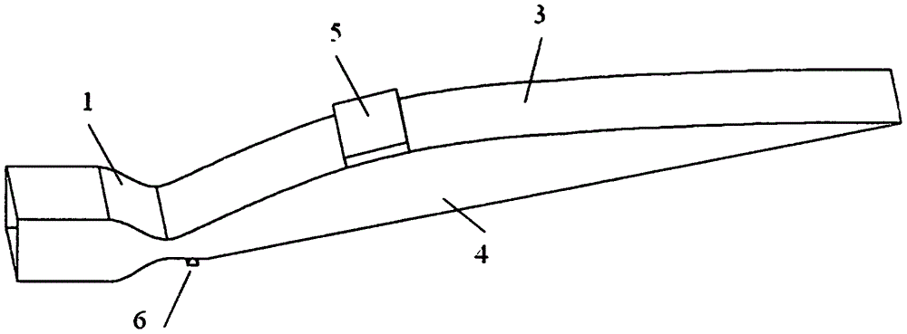
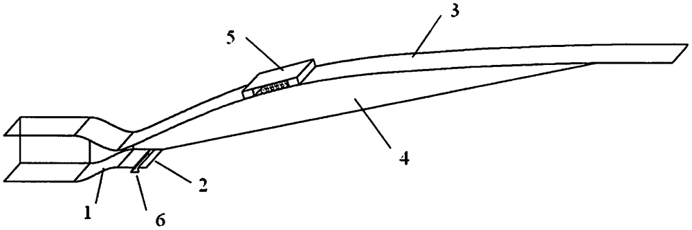
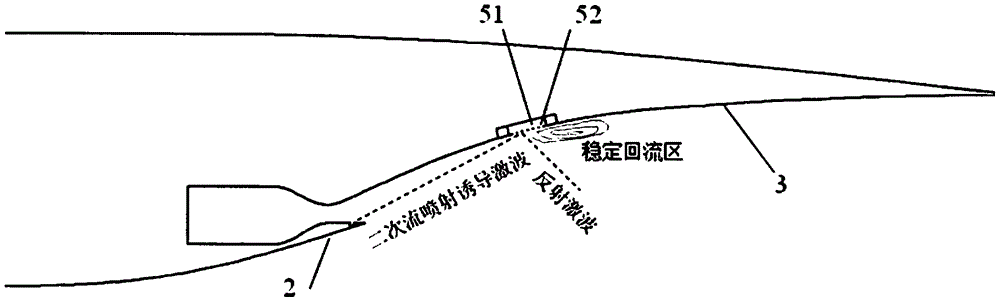
[0026] see Figure 1-7 As shown, in the present invention, a passive chamber structure is added to the upper expansion slope of the SERN, and a convergent secondary flow nozzle is opened on the lower slope of the SERN; under the premise of not significantly increasing the required control energy, a simple The passive cavity structure and the secondary flow injection device realize the control of the position of the oblique shock wave in the over-expansion state, thereby improving the pressure distribution of the nozzle on the single slope, increasing the thrust coefficient of the SERN in the over-expansion state, and improving the air-breathing high Thrust performance of a supersonic propulsion system in the transonic phase.

[0027] Please combine figure 1 As shown, the combined flow control structure o...


PUM


Abstract

The invention relates to a combined flow control method and structure for improving an SERN for a TBCC. The combined flow control method and the combined flow control structure are characterized in that a passive cavity structure is added on an upper expansion ramp of the SERN, and a convergent secondary flow nozzle is formed in a lower inclined plate of the SERN; and the oblique shock wave position is controlled in an overexpansion state through adopting the simple passive cavity structure and a secondary flow jet device under the precondition that the required control energy is not obviously added, the pressure distribution of a nozzle on a single ramp is improved, the thrust coefficient of the SERN in the overexpansion state is improved, and the thrust performance of an air-breathing hypersonic velocity propelling system in the transonic velocity stage is improved.

Description

technical field [0001] The present invention relates to the technical field of aero-engines, in particular to a single-slope expansion nozzle (Single Expansion Ramp Nozzle, SERN) flow control method and structure applied to an air-breathing hypersonic propulsion system (turbo ramjet, TBCC), specifically It is said to be a combined flow control technology that improves the thrust coefficient in the SERN overexpansion state. Background technique [0002] Air-breathing hypersonic aircraft (flying Mach number greater than 5) represents the strategic development direction of future military and civil aircraft, and is hailed as the third revolution in world aviation history after propeller and jet-propelled aircraft. In an air-breathing hypersonic vehicle, propulsion technology is the core key technology. Studies in various countries around the world have shown that the transonic region is the stage where the thrust margin (thrust and drag) of the vehicle is the lowest, and transo...

Claims


Application Information

Patent Timeline
IPC IPC(8): F02K1/28F02K1/78
CPCF02K1/28F02K1/78Y02T50/60
Inventor 张明阳周莉王占学祁少波史经纬孙啸林
Owner NORTHWESTERN POLYTECHNICAL UNIV
Why Eureka
Try Eureka