Propeller turbocharging device

A propeller and speed-increasing device technology, which is applied in the fields of ship engineering and fluid mechanics, can solve the problems of unused tangential and radial velocity components, and achieve the effects of improving energy utilization, increasing pressure, and increasing thrust coefficient

Pending Publication Date: 2022-04-12
TIANJIN RES INST FOR WATER TRANSPORT ENG M O T
View PDF8 Cites 2 Cited by
  • Summary
  • Abstract
  • Description
  • Claims
  • Application Information

AI Technical Summary

Problems solved by technology

[0008] The purpose of the present invention is to provide a marine propeller turbine speed-increasing device to solve the technical problem that the existing propeller only relies on the axial speed to provide propulsion, but the tangential and radial velocity components still contain a large amount of unused energy

Method used


Image

  • Propeller turbocharging device
  • Propeller turbocharging device
  • Propeller turbocharging device

Examples


Embodiment 1

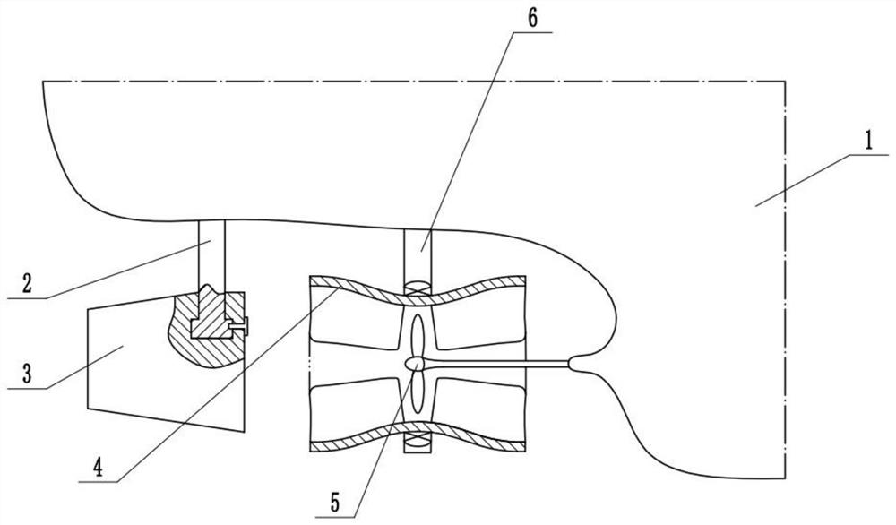
[0029] Such as figure 1 As shown, a marine propeller turbo speed increasing device includes a hull 1, a steering rudder driving rod 2 is installed on the hull 1, a steering rudder 3 is fixedly installed at the lower end of the steering rudder driving rod 2, and a bracket 6 and a bracket 6 are also installed on the hull 1. Propeller assembly 5, fairing assembly 4 is installed on the support 6, and one side of propeller assembly 5 is positioned at fairing assembly 4; Can realize the direction control to hull 1 by steering rudder 3; Steering rudder driving rod 2 can control steering rudder 3 Steering; the tangential and radial velocity components in the propeller wake can be extracted through the fairing assembly 4, and this energy can be used to increase the water inlet pressure of the propeller. On the one hand, the energy of the propeller wake can be extracted to improve energy utilization; On the one hand, the pressure at the water inlet of the propeller can be increased to e...

Embodiment 2

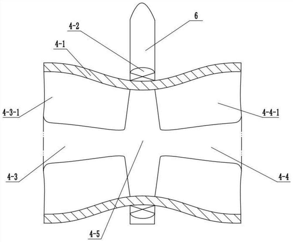
[0031] Such as figure 2 As shown, the fairing assembly 4 includes a fairing 4-1, and the fairing 4-1 is installed on the bracket 6 through a bearing 4-2, and a built-in cavity 4-5 is arranged in the fairing 4-1, and the propeller assembly 5 One side is located in the built-in cavity 4-5, and the built-in cavity 4-5 divides the fairing 4-1 into two regions: the wake area 4-3 and the turbine area 4-4; Concave barrel structure;

[0032] The wake area 4-3 is located on the side of the fairing 4-1 close to the steering rudder 3, and a plurality of rectifying blades 4-3-1 are evenly arranged in the circumferential direction of the wake area 4-3;

[0033] The turbine area 4-4 is on the side of the fairing 4-1 away from the steering rudder 3, and a plurality of turbine blades 4-4-1 are evenly arranged in the circumferential direction of the turbine area 4-4; the rectifying blades 4-3- 1 and the turbine blade 4-4-1 rotate in the opposite direction; the number and structure of the rect...

Embodiment 3

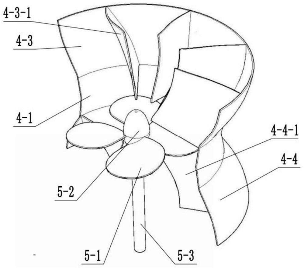
[0035] Such as image 3 and Figure 4 As shown, the propeller assembly 5 includes a propeller blade 5-1, a propeller blade hub 5-2 and a propeller blade drive shaft 5-3, and the propeller blade hub 5-2 is uniformly provided with a plurality of propeller blades 5-1 , the propeller blade hub 5-2 and the propeller blade 5-1 are located in the built-in cavity 4-5, and the propeller blade hub 5-2 is fixedly connected to the propeller blade drive shaft 5-3; the propeller blade hub 5-2 is Class cone; when in use, drive the propeller blade drive shaft 5-3 to rotate, and then drive the propeller blade hub 5-2 to rotate through the propeller blade drive shaft 5-3, and then drive the propeller blade 5-2 through the propeller blade hub 5-2 1 rotates, and then drives the water flow through the propeller blade 5-1, and then pushes the hull 1 forward through the reaction force of the water flow.

[0036] Working principle: drive the propeller blade transmission shaft 5-3 to rotate, and the...


PUM


Abstract

The invention belongs to the technical field of ship engineering and fluid mechanics, and particularly relates to a propeller turbocharging device. Comprising a ship body, a steering rudder driving rod is installed on the ship body, a steering rudder is fixedly installed at the lower end of the steering rudder driving rod, a support and a propeller assembly are further installed on the ship body, a fairing assembly is installed on the support, and one side of the propeller assembly is located in the fairing assembly. The propeller blade hub is driven to rotate through the propeller blade transmission shaft, the propeller blades are driven to rotate through the propeller blade hub, water flow is driven to flow through the propeller blades, and then the ship body is pushed to move forwards through the counter-acting force of the water flow. Tangential and radial velocity components in the wake flow of the propeller are extracted through a turbine area and turbine blades, and the energy is applied to increase of the water inlet pressure of the propeller. The turbine area can be driven by the wake flow area to actively provide kinetic energy and increase the water pressure at the front end of the propeller; and the direction of the ship body can be controlled through the steering rudder.

Description

technical field [0001] The invention belongs to the technical fields of ship engineering and fluid mechanics, and in particular relates to a propeller turbocharging device. Background technique [0002] The ocean development technology and equipment presented by the development of ocean engineering and science and technology in the world continue to improve, promoting the comprehensive development and utilization of ocean resources, and the development and utilization of ocean energy has become an important pillar for the development of ocean countries. [0003] A ship is composed of many parts. According to the function and use of each part, it can be comprehensively summarized into three parts: hull, ship power plant, and ship electrical. The hull is the basic part of the ship, which can be divided into the main part and the superstructure part. The main part generally refers to the part below the upper deck. It is a hollow body with a specific shape surrounded by the hul...

Claims


Application Information

Patent Timeline
Patent Type & Authority Applications(China)
IPC IPC(8): B63H5/15
Inventor 阳志文崔永刚
Owner TIANJIN RES INST FOR WATER TRANSPORT ENG M O T
Why Eureka
Try Eureka