
Method for improving thrust coefficient of pulse detonation engine and spraying pipe

A thrust coefficient and engine technology, which is applied in the direction of machines/engines, jet propulsion devices, etc., can solve problems such as inconsistent conclusions, and achieve the effects of improving the thrust coefficient, uniform control, and convenient thrust control

Inactive Publication Date: 2017-05-31
NANJING VOCATIONAL UNIV OF IND TECH
View PDF7 Cites 9 Cited by
  • Summary
  • Abstract
  • Description
  • Claims
  • Application Information

AI Technical Summary

Problems solved by technology

However, the large-span and unsteady characteristics of PDE’s temperature and pressure have always restricted the design of its unsteady nozzle. Operating parameters such as fuel, filling rate, frequency, altitude, and flight Mach number are closely related
According to relevant research, if the PDE adopts a fixed structure nozzle, there may even be a phenomenon that the same type of nozzle has completely opposite effects on the propulsion performance of the PDE under different working conditions of the engine.

Method used


Image

  • Method for improving thrust coefficient of pulse detonation engine and spraying pipe
  • Method for improving thrust coefficient of pulse detonation engine and spraying pipe
  • Method for improving thrust coefficient of pulse detonation engine and spraying pipe

Examples


Embodiment 1

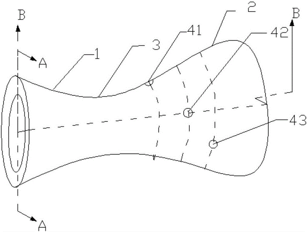
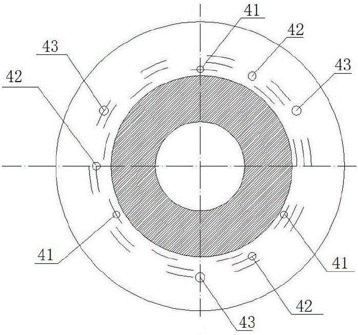
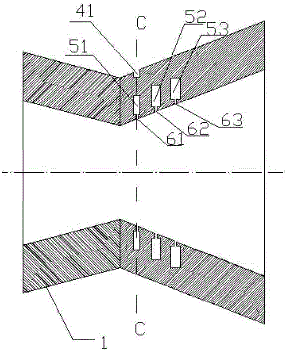
[0044] combine Figure 1-5 , three groups of annular jet flow holes are set in the pipe wall of the expansion section of the nozzle, and each group of jet flow holes is composed of an injection hole 4 , an annular channel 5 and an outflow annular hole 6 . Specifically, the first group of jet flow holes is composed of injection hole 41, annular channel 51 and outflow ring hole 61, the second group of jet flow holes is composed of injection hole 42, annular channel 52 and outflow ring hole 62, and the third group of jet flow holes is composed of injection hole 42, annular channel 52 and outflow ring hole 62. The group of jet flow holes is composed of injection holes 43, annular passages 53 and outflow annular holes 63. The annular passage 5 is an annular inner cavity in the pipe wall of the expansion section. A cylindrical hole communicating with the outside of the pipe, and the outflow ring hole 6 is a cylindrical hole uniformly distributed along the circumference that communic...

Embodiment 2

[0050] combine Figure 6-8 , three sets of annular jet flow holes are set between the inner and outer walls of the expanded section of the nozzle, and each set of jet flow holes is composed of cylindrical through holes 7 uniformly distributed along the circumference of the nozzle. The axial distance between the first group of jet flow holes 71 and the nozzle throat is 0.006-0.008m, and the axial distance between the second group of jet flow holes 72 and the first group of jet flow holes 71 is 0.006-0.008m Similarly, the third group of jet passage holes 73 has an axial distance from the second group of jet passage holes 72 of 0.006-0.008m.

[0051] Cylindrical through-holes 7 are provided along the radial direction of the nozzle, the diameter of cylindrical through-holes 7 is preferably 0.001-0.002m, and the distance between adjacent cylindrical through-holes in each group of jet through-holes is 0.002-0.004m, but it is certainly not limited thereto The distance, as long as th...


PUM

PropertyMeasurementUnit
Diameteraaaaaaaaaa
Depthaaaaaaaaaa

Abstract

The invention provides a method for improving a thrust coefficient of a pulse detonation engine and a spraying pipe. On the wall face of an expanding segment of the spraying pipe of the tail portion of the pulse detonation engine, at least two annular jet flows are introduced into the spraying pipe at an equal interval in the axial direction; the jet flow closest to the throat portion of the spraying pipe needs to be arranged before the occurring position of an over-expansion phenomenon; each annular jet flow is evenly arranged in the circumferential direction; and the jet flows enter the spraying pipe in the radial direction perpendicular to the center axis of the spraying pipe. According to the method, a traditional Laval spraying pipe expanding segment wall face is structurally improved, a small stream of annular subsonic speed jet flow with the mach number greatly different from that of a center main flow is introduced at a specific position, a new control face is formed on the outer side of the main flow, the actual expansion ratio of the main flow is made to be closer to an optimal value, and the thrust coefficient of the engine is effectively improved. Meanwhile, because the introduced jet flows are annular jet flows, the outlet gas flows of the spraying pipe are still in an axisymmetry type effect, and the thrust of the engine is in the axis direction of the spraying pipe.

Description

technical field [0001] The invention belongs to the technical field of engine tail nozzles, and in particular relates to a method for increasing the thrust coefficient of a pulse detonation engine and an unsteady annular jet flow control nozzle suitable for the method. Background technique [0002] The research on steady nozzle design based on aerodynamics has been relatively mature, but the nozzle design for unsteady flow has not made a breakthrough so far. With the research and application of pulse detonation engine (Pulse Detonation Engine, PDE for short), pulse engine and other unsteady engines, the nozzle design in unsteady flow has become an important technology that researchers need to break through. The thermal energy generated in the combustion chamber of the unsteady engine is fully converted into the power energy for increasing the thrust of the engine. This type of engine is different from conventional engines. The flow field in the combustion chamber and the no...

Claims


Application Information

Patent Timeline
IPC IPC(8): F02K1/28
CPCF02K1/28
Inventor 王研艳杨燕张玲王斌翁春生
Owner NANJING VOCATIONAL UNIV OF IND TECH
Learn More