
Barrier-free used concealedly-installed control valve

A barrier-free, valve control technology, applied in valve operation/release device, valve details, multi-port valve, etc., can solve problems such as poor body, no safety measures, and low shower water temperature, and achieve convenient opening and switching operations, The effect of simplifying the space effect and ensuring the convenience

Active Publication Date: 2016-10-12
FUJIAN XIHE SANITARY WARE TECH
View PDF8 Cites 3 Cited by
  • Summary
  • Abstract
  • Description
  • Claims
  • Application Information

AI Technical Summary

Problems solved by technology

[0004] However, the disadvantages of the above-mentioned invention are that the handle and the handle seat are always protrudingly arranged on the wall, occupying a certain space; If it is opened, it may cause burns
[0005] Most of the thermostatic faucets in the prior art have a safety button to prevent burns when the temperature is increased, that is, upward beyond the default temperature range, but there is no insurance measure when the temperature is lowered, that is, downward beyond the default temperature range. It may cause the shower water temperature to drop sharply inadvertently; and as we all know, the impact of cold water often causes adverse stimuli to the body, thus bringing corresponding stress responses, especially for special users such as the three-high crowd and the elderly. dangerous

Method used


Image

  • Barrier-free used concealedly-installed control valve
  • Barrier-free used concealedly-installed control valve
  • Barrier-free used concealedly-installed control valve

Examples


Embodiment Construction

[0047] The present invention will be further described in detail below in conjunction with the accompanying drawings and embodiments.

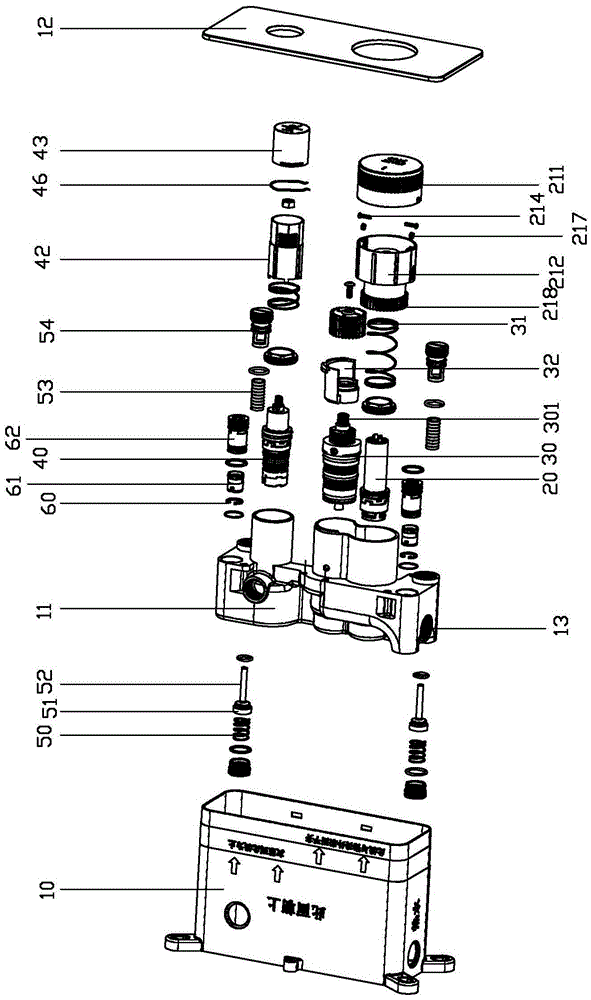
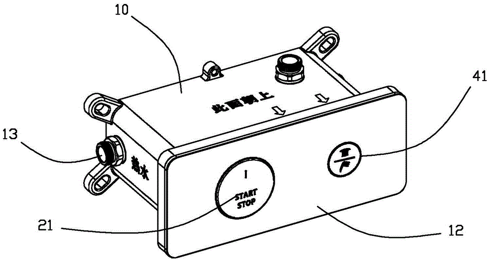
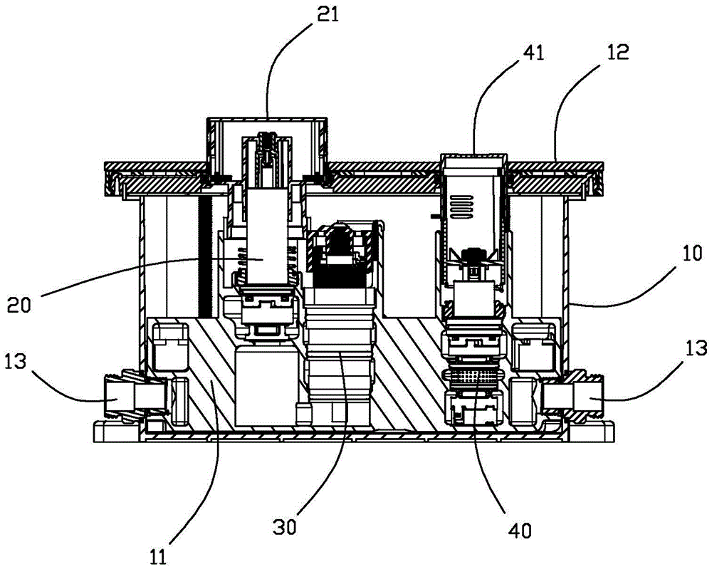
[0048] In order to solve the shortcomings of the prior art concealed faucets, such as the inability to prevent cold, the inability to realize "secondary opening and anti-scalding", and the difficulty of operating with parts other than fingers, the present invention provides a concealed control valve for barrier-free use, such as figure 1 , figure 2 , image 3 As shown, it includes a concealed box body 10, a concealed body 11, and a rotary control thermostatic valve 30. The thermostatic valve 30 is installed in the concealed body 11, and the thermostatic valve 30 is arranged on the water inlet and outlet channels of the concealed body 11. Between, the concealed installation body 11 is installed in the concealed installation box body 10 . The water inlet channel of the present invention includes a hot water inlet channel and a cold water inle...


PUM

PropertyMeasurementUnit
Diameteraaaaaaaaaa

Abstract

The invention relates to a barrier-free used concealedly-installed control valve. The control valve comprises a concealedly-installed box, a concealedly-installed body and a rotary-control type thermostatic valve. The thermostatic valve is installed in the concealedly-installed body and arranged between a water inlet channel and a water outlet channel of the concealedly-installed body. The concealedly-installed body is installed in the concealedly-installed box. A pressing type switch valve is arranged between the thermostatic valve and the water inlet channel. A rotary hand wheel is arranged at the end of the switch valve. Linkage is achieved between the rotary hand wheel and a thermoregulation assembly of the thermostatic valve. The rotary hand wheel is pressed once, the switch valve is closed, the thermostatic valve and the water inlet channel are blocked, and the rotary hand wheel is not higher than a panel of the concealedly-installed box. The rotary hand wheel is pressed again, the switch valve is opened, the thermostatic valve communicates with the water inlet channel, and the rotary hand wheel extends out of the panel of the concealedly-installed box. According to the barrier-free used concealedly-installed control valve, barrier-free operation can be conducted. The control valve has anti-scalding and anti-cold functions and a secondary starting anti-scalding function, and anti-scalding and anti-cold effects are both achieved through arrangement of exceeding prompting tap positions, namely, the possibility that water temperature is adjusted to be low due to the fact that the hand wheel is accidentally driven by clothes, a bath towel and the like to rotate is avoided completely.

Description

technical field [0001] The invention relates to a water outlet control valve in the field of sanitary ware, more specifically, to a concealed control valve for barrier-free use. Background technique [0002] The mechanical button faucets in the prior art ignore the experience of users who are inconvenient to use their fingers. When the fingers are inconvenient to use, it will be difficult to switch the button faucet. [0003] The operating handles of the concealed thermostatic faucet in the prior art are all protruding from the wall, forming a protruding shape, occupying space, and forming an obstacle. Moreover, it cannot be avoided that it is turned off when the water is adjusted to the highest temperature, causing the risk of scalding when the user opens it next time. Chinese invention patent application 201210459620.2 discloses a concealed thermostatic faucet with no gap installation combined with an anti-scald protection button structure, including a thermostatic faucet...

Claims


Application Information

Patent Timeline
IPC IPC(8): F16K11/22F16K31/44F16K31/60
CPCF16K11/22F16K31/44F16K31/60
Inventor 林孝发林孝山李帅宇刘启乔邓小清
Owner FUJIAN XIHE SANITARY WARE TECH
Learn More