Hydraulic control device

A control device, hydraulic technology, applied in valve device, valve operation/release device, valve details, etc., can solve problems such as overshoot effect, damage to household appliances, unstable water pressure, etc., to prevent overshoot effect, prevent Siphon effect, the effect of preventing water backflow

Active Publication Date: 2016-10-12
JINHUA HONGCHANG ELECTRLCAL EQUIP CO LTD
View PDF9 Cites 1 Cited by
  • Summary
  • Abstract
  • Description
  • Claims
  • Application Information

AI Technical Summary

Problems solved by technology

[0002] In existing home appliances such as washing machines, dishwashers, and smart toilets, water valves are needed to control the inflow and outflow of water bodies and the flow rate of water bodies. Since water pressure varies greatly in different regions, and in some regions There is unstable water pressure
When there is no water pressure, the water pressure is unstable, or the water inlet pressure drops sharply, a negative pressure will be generated at the water inlet and outlet of the household appliance. A siphon phenomenon is generated, causing the water in the home appliance to flow back, and the returned water will pollute the water resources at the water inlet
And when the pressure of the water body suddenly increases sometimes, if it is not properly controlled, it will also cause an overshoot effect, which will damage the home appliances.
[0003] In the prior art, although there are different technical solutions to solve the problems of overshoot prevention and water backflow prevention, the existing technical solutions are not effective, the structure is relatively cumbersome, they do not have universal applicability, and they are costly and poor in versatility , manufacturing troubles, complex product structure, and complex assembly process, so in the prior art, it is still impossible to effectively solve the problems of preventing water overflushing and preventing water backflow in existing household appliances such as washing machines, dishwashers, and smart toilets.

Method used


Image

  • Hydraulic control device
  • Hydraulic control device
  • Hydraulic control device

Examples


Embodiment Construction

[0030] The present invention will be further described below in conjunction with the accompanying drawings.

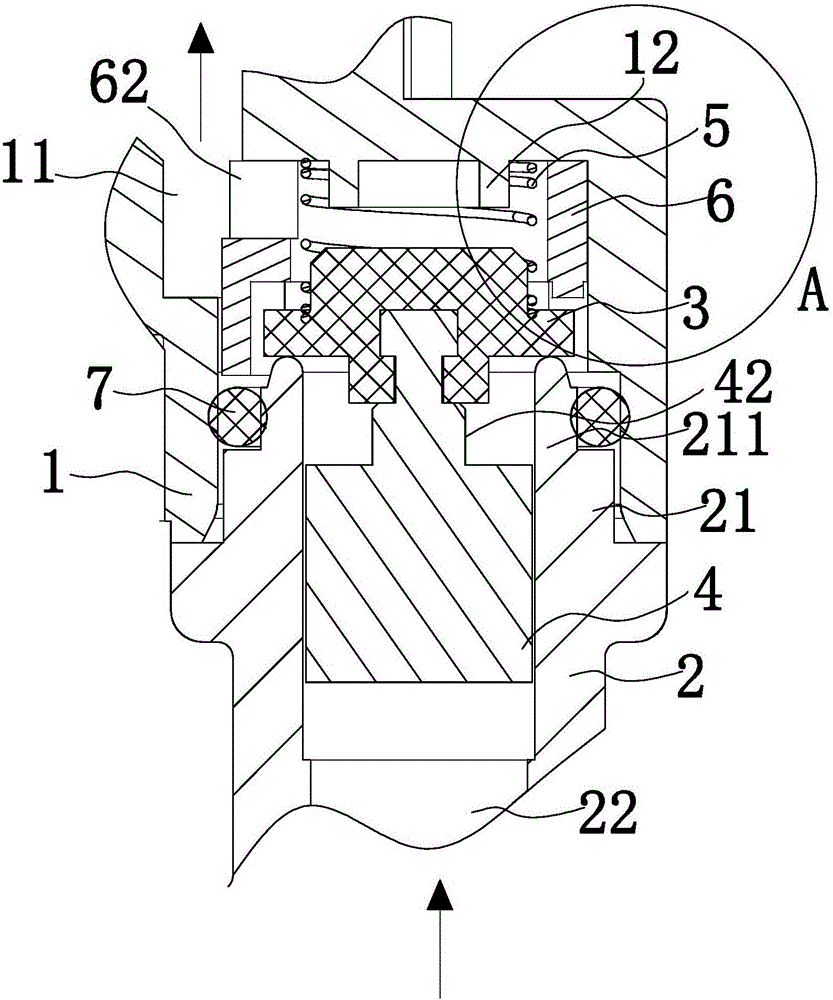
[0031] like figure 1 As shown, the present invention includes a housing, the housing includes an upper housing 1 and a lower housing 2, the lower housing 2 is provided with a socket section 21 that is socketed inside the upper housing 1, and the lower housing 2 is provided with Water inlet, the upper shell 1 is provided with a water outlet 11, and the sleeve section 21 is provided with a water inlet channel 22 connected with the water inlet.

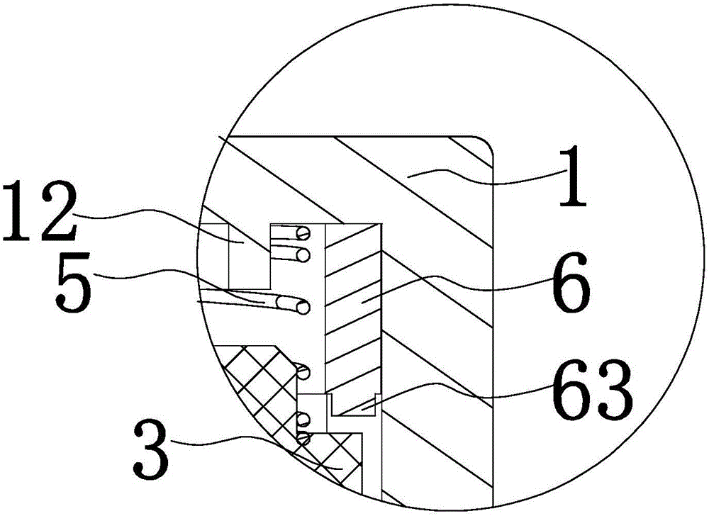
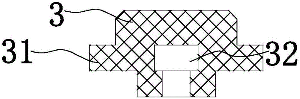
[0032] like figure 1 As shown, the casing of the present invention is provided with an anti-backwater mechanism, and the anti-backwater mechanism in the present invention includes: a gasket 3 arranged between the sleeve section 21 and the upper casing 1; abutting against the gasket 3 and the upper casing Return spring 5 between body 1. Wherein the gasket 3 has an anti-backwater level covered on the end surface of the sleeve se...


PUM


Abstract

The invention discloses a hydraulic control device. The device comprises a shell, the shell comprises an upper shell body and a lower shell body, the lower shell body is provided with a sleeve section sleeved with the upper shell body, a water inlet is formed in the lower shell body, a water outlet is formed in the upper shell body, a water inlet channel connected with the water inlet is arranged in the sleeve section, and a water backflow prevention mechanism is arranged in the shell. The water backflow prevention mechanism comprises a sealing pad between the sleeve section and the upper shell body, and a return spring abutting between the sealing pad and the upper shell body. The sealing pad is provided with a water backflow prevention position driven by the return spring and covering the end face of the sleeve section, and a water passing position driven by water flow in the water inlet channel and separated from the end face of the sleeve section. The hydraulic control device can effectively prevent the action of water backflow.

Description

technical field [0001] The invention belongs to the technical field of valves, and in particular relates to a hydraulic control device. Background technique [0002] In existing home appliances such as washing machines, dishwashers, and smart toilets, water valves are needed to control the inflow and outflow of water bodies and the flow rate of water bodies. Since water pressure varies greatly in different regions, and in some regions There is unstable water pressure. When there is no water pressure, the water pressure is unstable, or the water inlet pressure drops sharply, a negative pressure will be generated at the water inlet and outlet of the household appliance. A siphon phenomenon is generated, causing the water in the home appliance to flow back, and the backflowing water will pollute the water resources at the water inlet. And when the pressure of the water body suddenly increases sometimes, if it is not properly controlled, it will also cause an overshoot effect,...

Claims


Application Information

Patent Timeline
Patent Type & Authority Applications(China)
IPC IPC(8): F16K31/363
CPCF16K31/363
Inventor 罗小春方玉萍范晓鸿余一民
Owner JINHUA HONGCHANG ELECTRLCAL EQUIP CO LTD
Why Eureka
Try Eureka