
A kind of oil fume purification device

A technology of oil fume purification and oil tank, which is applied in the field of air purification, can solve the problems of difficult replacement of purification parts, inconvenient cleaning of oil stains, difficulty in disassembly and assembly of oil fume purification devices, etc., and achieves the effect of convenient maintenance and cleaning

Active Publication Date: 2018-06-26
ZHEJIANG UNIV KUNSHAN INNOVATION INST
View PDF7 Cites 0 Cited by
  • Summary
  • Abstract
  • Description
  • Claims
  • Application Information

AI Technical Summary

Problems solved by technology

[0002] With the development of the economy, people pay more and more attention to health. The kitchen, as a place that must pass through every day, has attracted people's attention. According to reports, the air pollution in the kitchen causes millions of deaths every year around the world. How to control the air pollution in the kitchen is now urgent. The problem that needs to be solved. In response to this phenomenon, a variety of oil fume purification devices have appeared on the market, which has alleviated people’s concerns about the air environment in the kitchen to a certain extent. However, most of the oil fume purification devices have the following problems: 1. Disassembly of the oil fume purification device Difficult to install and difficult to replace key purification parts; 2. Oil stains are inconvenient to clean

Method used


Image

  • A kind of oil fume purification device
  • A kind of oil fume purification device
  • A kind of oil fume purification device

Examples


Embodiment 1

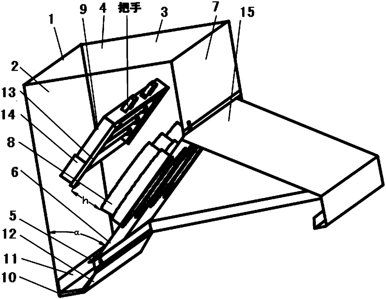
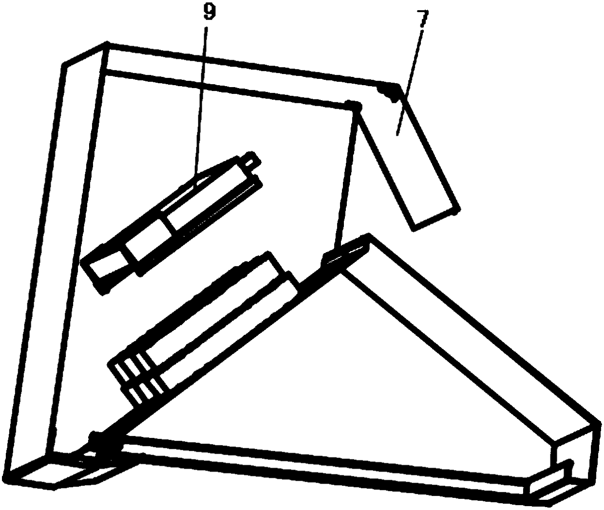
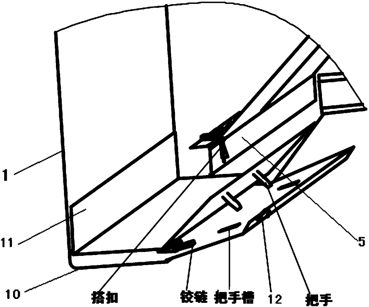
[0027] Such as figure 1 The shown oil fume purification device includes a backboard 1 fixed on the wall, a left wallboard 2 connected to the backboard 1, a right wallboard 3, a top board 4, and a fixing board installed between the left and right wallboards 3 5. A removable oil tank is provided between the lower end of the back plate 1 and the fixed plate 5. An oil absorbing panel 6 is installed on the fixed plate 5. One end of the oil absorbing panel 6 is hinged on the fixed plate 5. The rod 16 is connected with the left wall plate 2 and the right wall plate 3, and a turning plate 7 is arranged between the oil-absorbing panel 6 and the top plate 4, and one end of the turning plate 7 is hinged on the top plate 4, and the back plate 1, the left Wall plate 2, right wall plate 3, top plate 4, oil-absorbing panel 6, turning plate 7 and oil tank constitute a casing with a cavity inside; said oil-absorbing panel 6 is provided with an oil-absorbing hole, and the inner cavity side of s...

Embodiment 2

[0036] Such as Figure 4The shown oil fume purification device includes a backboard 1 fixed on the wall, a left wallboard 2 connected to the backboard 1, a right wallboard 3, a top board 4, and a fixing board installed between the left and right wallboards 3 5. A removable oil tank is provided between the lower end of the back plate 1 and the fixed plate 5. An oil absorbing panel 6 is installed on the fixed plate 5. One end of the oil absorbing panel 6 is hinged on the fixed plate 5. The rod 16 is connected with the left wall plate 2 and the right wall plate 3, and a turning plate 7 is arranged between the oil-absorbing panel 6 and the top plate 4, and one end of the turning plate 7 is hinged on the top plate 4, and the back plate 1, the left Wall plate 2, right wall plate 3, top plate 4, oil-absorbing panel 6, turning plate 7 and oil tank constitute a casing with a cavity inside; said oil-absorbing panel 6 is provided with an oil-absorbing hole, and the inner cavity side of s...


PUM


Abstract

The invention discloses a novel lampblack purification device. The novel lampblack purification device comprises a back plate, a left wall plate, a right wall plate, a top plate and a fixing plate, wherein the back plate is fixed on a wall; the left wall plate, the right wall plate and the top plate are connected with the back plate; the fixing plate is mounted between the left wall plate and the right wall plate; an oil groove capable of being taken out is formed between the lower end of the back plate and the fixing plate; a lampblack suction panel is mounted on the fixing plate; one end of the lampblack suction panel is hinged to the fixing plate and is also connected with the left wall plate and the right wall plate through a retractable rod; a turnover plate is arranged between the lampblack suction panel and the top plate; one end of the turnover plate is hinged to the top plate; a lampblack suction hole is formed in the lampblack suction panel; a draught fan is mounted on an inner cavity side of the lampblack suction hole; a photolysis frame assembly is arranged in a cavity of an enclosure; and the photolysis frame assembly is fixed on the left wall plate and the right wall plate. With the adoption of the novel lampblack purification device disclosed by the invention, purification of a kitchen air environment is realized, and tracing, installation and fixation, maintenance and washing of the photolysis frame assembly and the draught fan are relatively convenient.

Description

technical field [0001] The invention relates to an oil fume purification device, which belongs to the field of air purification. Background technique [0002] With the development of the economy, people pay more and more attention to health. The kitchen, as a place that must pass through every day, has attracted people's attention. According to reports, the air pollution in the kitchen causes millions of deaths every year around the world. How to control the air pollution in the kitchen is now urgent. The problem that needs to be solved. In response to this phenomenon, a variety of oil fume purification devices have appeared on the market, which has alleviated people’s concerns about the air environment in the kitchen to a certain extent. However, most of the oil fume purification devices have the following problems: 1. Disassembly of the oil fume purification device Difficult to install, and difficult to replace key purification parts; 2. Oil stains are inconvenient to clea...

Claims


Application Information

Patent Timeline
Patent Type & Authority Patents(China)
IPC IPC(8): F24C15/20
CPCF24C15/2092
Inventor 黄保乾王晓剑牛英朋姚军
Owner ZHEJIANG UNIV KUNSHAN INNOVATION INST
Learn More