Imaging lens and imaging apparatus
A technology of imaging lens and imaging device, which is applied to optical elements, optics, instruments, etc., can solve the problems of increasing the load of the driving system and the weight of the focusing group, and achieve the goal of suppressing the increase in diameter, small F value, and maintaining performance. Effect
- Summary
- Abstract
- Description
- Claims
- Application Information
AI Technical Summary
Problems solved by technology
Method used
Image
Examples
Embodiment 1
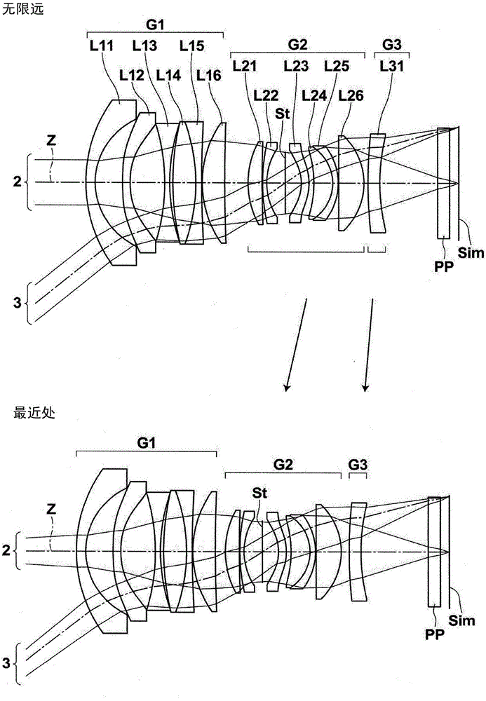
[0117] figure 1 The structure of the imaging lens of Example 1 is shown. It should be noted, figure 1 The detailed descriptions of each lens group and each lens in the structure are as above, so repeated descriptions are omitted here. Tables 1 to 3 below show numerical data showing the detailed configuration of the imaging lens of Example 1. Table 1 shows basic lens data, Table 2 shows aspheric coefficients, and Table 3 shows the values of various factors and variable facet intervals.
[0118] The column of Si in Table 1 shows the numbering of the faces of the constituent elements such that the object-side face of the constituent element closest to the object side is the first and increases sequentially toward the image side. i (i=1, 2, 3, ...) surface numbers, the Ri column shows the radius of curvature of the i-th surface, and the Di column shows the i-th surface and the i+1-th surface on the optical axis The plane spacing on Z, the Ndj column shows the jth (j=1, 2, 3,...
Embodiment 2
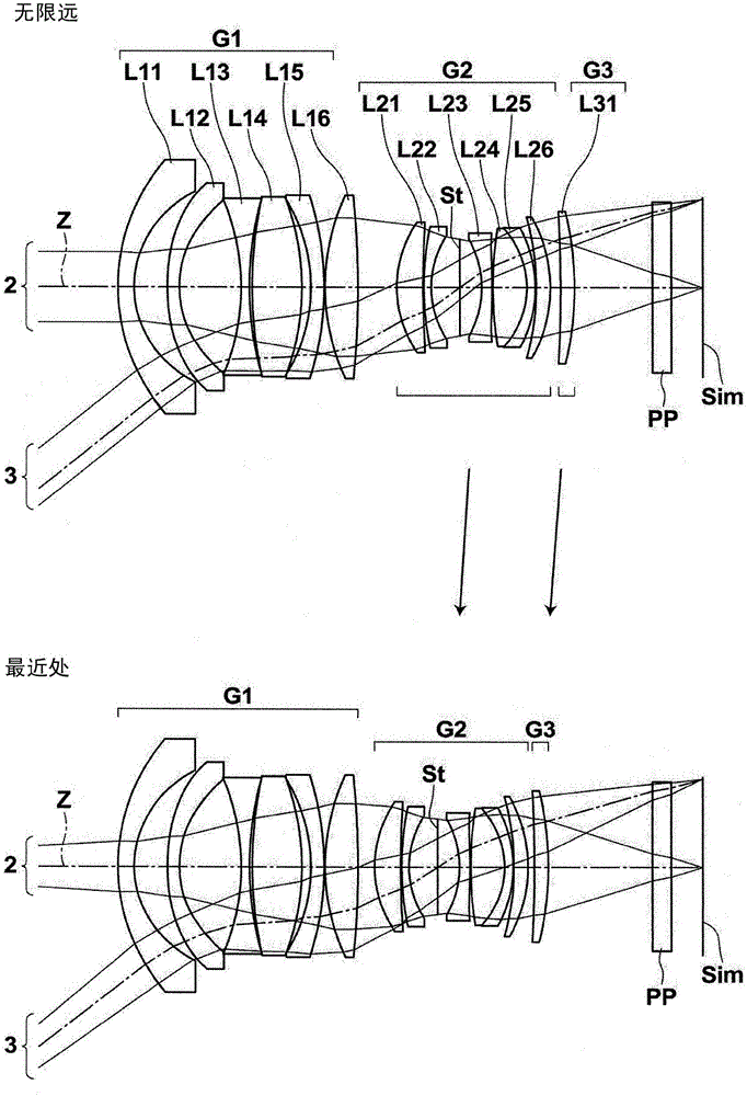
[0142] figure 2 The structure of the imaging lens of Example 2 is shown. The imaging lens of Example 2 is composed of three lens groups of the first lens group G1 to the third lens group G3. At the time of focusing, the first lens group G1 is fixed, and the second lens group G2 and the third lens group G3 are moved such that the mutual interval in the optical axis direction changes. The number of lenses each of the first lens group G1 to the third lens group G3 has is the same as that of the first embodiment. Table 4 shows basic lens data of the imaging lens of Example 2, Table 5 shows aspheric coefficients, and Table 6 shows values of various factors and variable surface intervals. Figure 6 Various aberration diagrams of the imaging lens of Example 2 are shown.
[0143] 【Table 4】
[0144] Example 2
[0145] Si
Ri
Di
Ndj
νdj
1
33.1597
2.4333
1.80518
25.42
2
17.4979
5.0163
*3
41.2286
1.8000
...
Embodiment 3
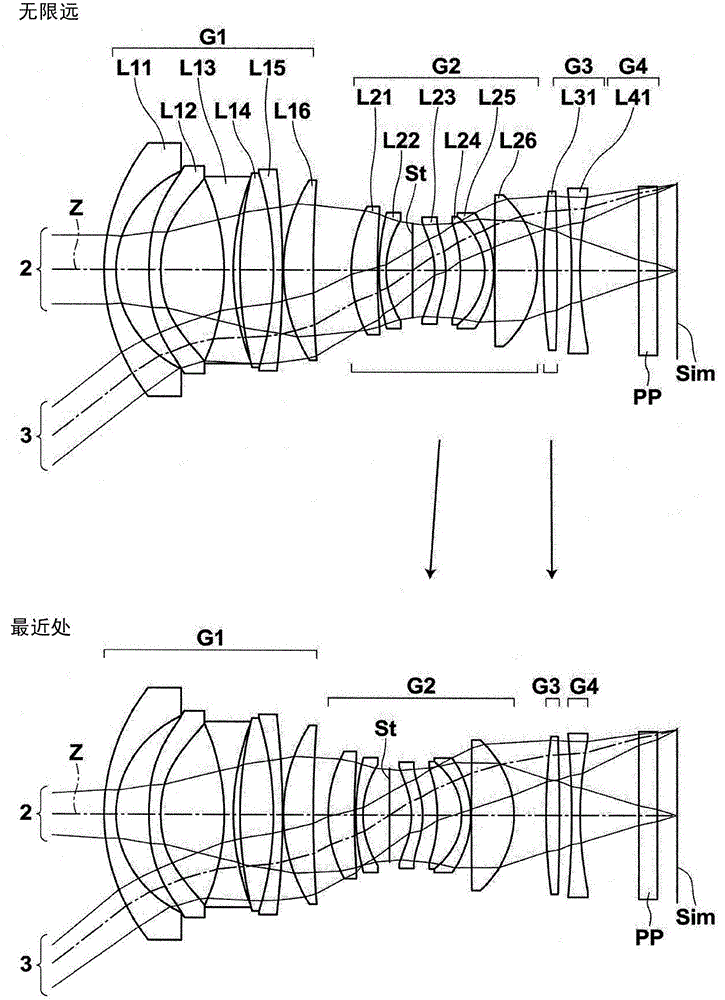
[0153] image 3 The structure of the imaging lens of Example 3 is shown. The imaging lens of Example 3 is composed of four lens groups of the first lens group G1 to the fourth lens group G4. When focusing, the first lens group G1 and the fourth lens group G4 are fixed, and the second lens group G2 and the third lens group G3 are moved such that the mutual interval in the optical axis direction changes. The fourth lens group G4 is composed of only the lens L41. The number of lenses each of the first lens group G1 to the third lens group G3 has is the same as that of the first embodiment. Table 7 shows basic lens data of the imaging lens of Example 3, Table 8 shows aspherical coefficients, and Table 9 shows values of various factors and variable surface intervals. Figure 7 Various aberration diagrams of the imaging lens of Example 3 are shown.
[0154] 【Table 7】
[0155] Example 3
[0156] Si
Ri
Di
Ndj
νdj
1
35.7060
1.8000
1.9211...
PUM
 Abstract
Description
Claims
Application Information
 - R&D
- Intellectual Property
- Life Sciences
- Materials
- Tech Scout
- Unparalleled Data Quality
- Higher Quality Content
- 60% Fewer Hallucinations
Browse by: Latest US Patents, China's latest patents, Technical Efficacy Thesaurus, Application Domain, Technology Topic, Popular Technical Reports.
© 2025 PatSnap. All rights reserved.Legal|Privacy policy|Modern Slavery Act Transparency Statement|Sitemap|About US| Contact US: help@patsnap.com


