
Microscope Auxiliary Device to Eliminate Blind Spots on the Surface of the Object to Be Tested

An auxiliary device and object surface technology, applied in microscopes, instruments, optics, etc., can solve the problems of damaging the original structure of the microscope, expensive microscopes, and reduced imaging quality, and achieve the effects of simple installation, stable structure, and increased information volume

Active Publication Date: 2019-01-11
中科伊和智能医疗科技(佛山)有限公司
View PDF5 Cites 0 Cited by
  • Summary
  • Abstract
  • Description
  • Claims
  • Application Information

AI Technical Summary

Problems solved by technology

However, the microscope is expensive and only available for fixed models
For reflection microscopes that are common on the market, if this technology is used to modify them, there is a risk of destroying the existing optical system, resulting in reduced image quality and damage to the original structure of the microscope

Method used


Image

  • Microscope Auxiliary Device to Eliminate Blind Spots on the Surface of the Object to Be Tested
  • Microscope Auxiliary Device to Eliminate Blind Spots on the Surface of the Object to Be Tested
  • Microscope Auxiliary Device to Eliminate Blind Spots on the Surface of the Object to Be Tested

Examples


Embodiment Construction

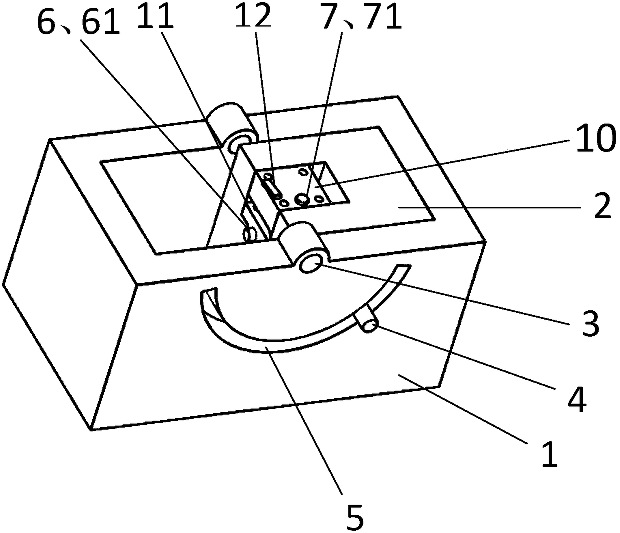
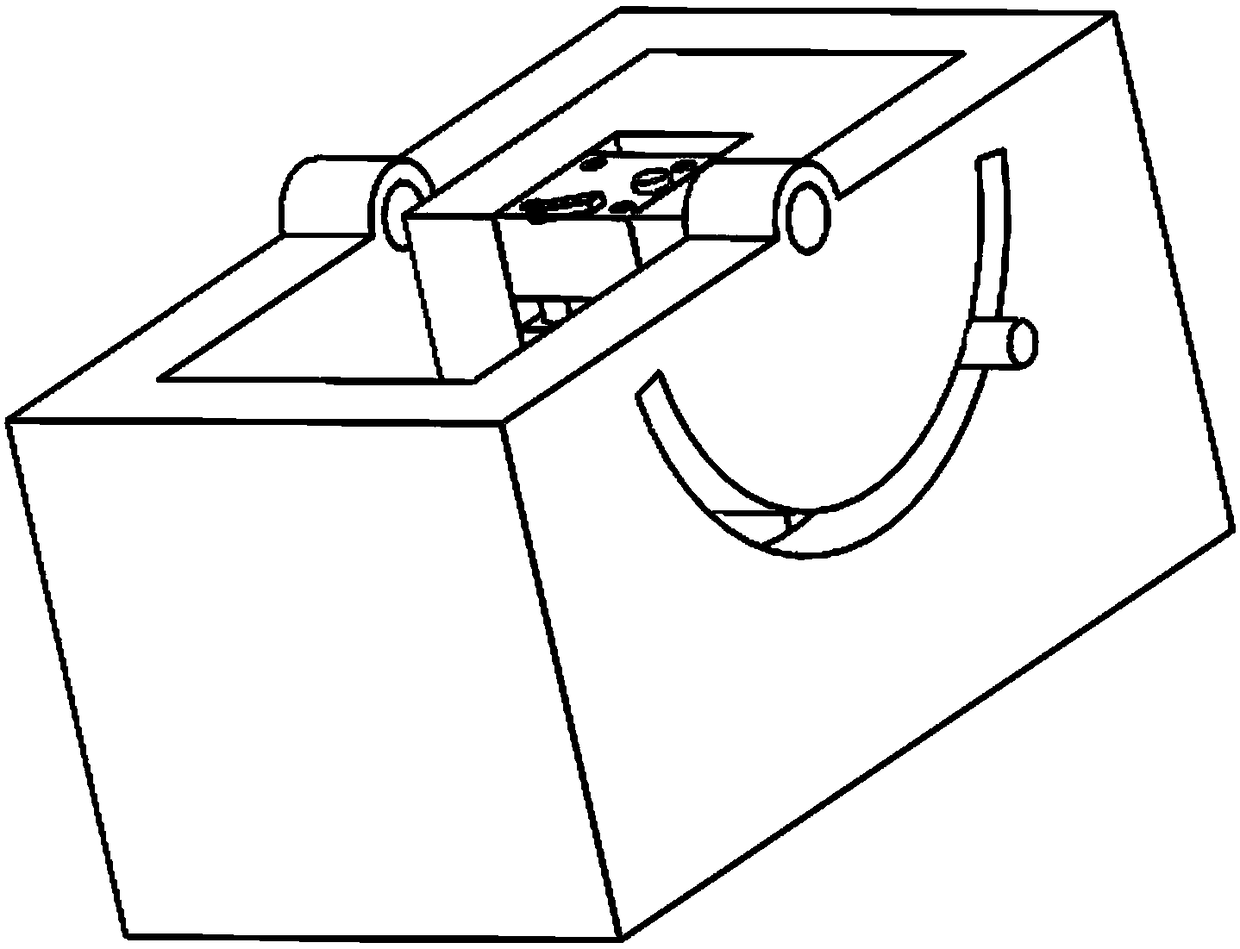
[0026] Such as Figure 2-Figure 6 As shown, the upper surface of the base is provided with a groove and a rotating shaft crossing the groove, and one corner of the rotating base is installed in the groove through the rotating shaft, and the rotating base can be freely rotated relative to the groove by driving the rocker; The base body is provided with a gap at the position where the rotating shaft is located, and a shelf bracket is fixedly arranged on the concave surface formed by the gap, and the shelf and the shelf bracket are kept at a distance from the inner elevation of the concave surface formed by the gap; The component and the vertical adjustment component are installed and connected with the shelf bracket.

[0027] The horizontal adjustment assembly specifically includes an adjustment screw that runs through the shelf support horizontally from the outside of the gap to the inside of the gap, and a spring that is horizontally sleeved on the adjustment screw near the en...


PUM


Abstract

The invention provides a microscope auxiliary device used for eliminating blind spots of a surface of a measured object. The device comprises a foundation, a rotation substrate, a rotation driving mechanism, a carrying stand and a carrying stand support, wherein an upper surface of the foundation is provided with a groove and a rotation shaft penetrating through the groove, the rotation substrate is mounted in the groove through the rotation shaft and can freely rotate relative to the groove under the action of the rotation driving mechanism, the rotation substrate is provided with a notch at the position of the rotation shaft, an inner concave surface of the notch is fixedly equipped with the carrying stand support through a horizontal adjustment assembly, the carrying stand is connected with the carrying stand support through a vertical adjustment assembly, and an upper surface of the carrying stand is provided with a mechanism used for disposing and fixing the measured object. Only through mounting the device on the surface of the microscope carrying stand, the measured object can be observed in an omnibearing mode through controlling the device, blind spots of the surface of the measured object can be eliminated, and the omnibearing information of the measured object can be complemented.

Description

technical field [0001] The invention relates to a microscope auxiliary device. Background technique [0002] The principle of the reflected light microscope to observe objects is: an external light source is irradiated on the surface of the object, and after being reflected by the object, it enters the microscope imaging system to form a magnified image. But you can only observe the image of the light source directly irradiating the surface area of ​​the object. For some special holes and grooves, because the side walls are chamfered, the incident light is blocked by the upper surface of the holes and grooves, and the light cannot completely enter the holes and grooves. bottom and side walls. When observing objects with a microscope, these unobservable areas form blind spots, resulting in the loss of information about the measured object. [0003] In order to eliminate this test phenomenon, the HUVITZ digital microscope in South Korea can realize all-round observation of t...

Claims


Application Information

Patent Timeline
Patent Type & Authority Patents(China)
IPC IPC(8): G02B21/26
CPCG02B21/26
Inventor 李秀山王贞福杨国文
Owner 中科伊和智能医疗科技(佛山)有限公司
Learn More