A Sliding Circular Synthetic Aperture Radar Imaging Method

A synthetic aperture radar and sliding technology, which is applied in the field of microwave imaging technology for earth observation, can solve the problem of unfavorable observation application without sliding circular synthetic aperture radar, and the inability to realize large-strip high-resolution omnidirectional imaging observation To achieve the effect of large-scale high-resolution omni-directional circumferential imaging data acquisition and imaging processing

Active Publication Date: 2016-09-28
INST OF ELECTRONICS CHINESE ACAD OF SCI
View PDF4 Cites 0 Cited by
  • Summary
  • Abstract
  • Description
  • Claims
  • Application Information

AI Technical Summary

Problems solved by technology

[0002] In the mid-to-late 1990s, Falconer et al. first proposed the three-dimensional imaging method of Circular Synthetic Aperture Radar (CSAR for short) (see Falconer D G, Moussally G J. Tomographic imaging of radar sata gathered on a circular flight path about a three -dimensional target zone.Proceedings of SPIE1995,Apr.,1995.), the radar sensor performs 360°circular motion with the platform, and the beam always points to the same scene area to observe the area, so as to realize the three-dimensional imaging data acquisition of the observation area; subsequently, Soumekh In order to achieve a finer three-dimensional imaging capability, proposed the E-CSAR (Elevation Circular SAR, referred to as E-CSAR) imaging method (see SoumekhM. Synthetic aperture radar signal processing with matlab algorithms. NewYork; Wiley.1999.), but These two imaging methods are mainly to realize the all-round imaging capability of a certain range of observation scenes in the central area of ​​the circular flight track. The imaging area depends entirely on the radar antenna pitch and track -3dB beam width. For a single flight, it cannot Realize large-strip high-resolution omni-directional imaging observation
At present, the sliding circular synthetic aperture radar imaging method has not been given at home and abroad. Therefore, it is still unable to solve the prominent contradiction between omni-directional high-resolution imaging and large-scale observation.
[0005] The main technical defect of the existing technology: Circular Synthetic Aperture Radar (CSAR) imaging area mainly depends on the radar antenna pitch-azimuth 3dB beam width, making its observation area stay in the central area within the range of the flight track for a long time , which is not conducive to the practical application of large-scale high-resolution earth observation

Method used


Image

  • A Sliding Circular Synthetic Aperture Radar Imaging Method
  • A Sliding Circular Synthetic Aperture Radar Imaging Method
  • A Sliding Circular Synthetic Aperture Radar Imaging Method

Examples


Embodiment Construction

[0018] In order to make the object, technical solution and advantages of the present invention clearer, the present invention will be described in further detail below in conjunction with specific embodiments and with reference to the accompanying drawings.

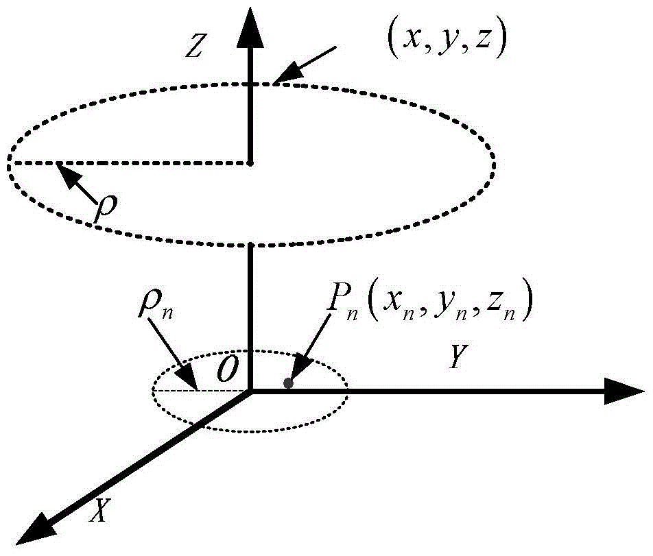
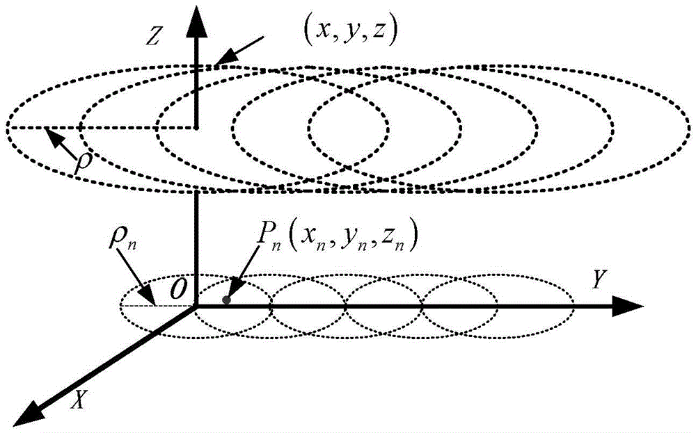
[0019] The present invention provides a kind of new sliding type circumferential synthetic aperture radar imaging method, with conventional circumferential synthetic aperture radar imaging (such as figure 1 shown) compared with the sliding circular synthetic aperture radar imaging (Sliding CSAR, referred to as S-CSAR) by "sliding" forward, such as figure 2 As shown, the imaging area can be greatly expanded while retaining its advantages of conventional imaging.

[0020] For the convenience of description, it is explained in combination with the imaging geometry of the sliding circular synthetic aperture radar. Such as figure 2 As shown, when the platform moves, the three-dimensional position coordinates of the radar t...


PUM


Abstract

The invention discloses a method for imaging circumferential synthetic aperture radar. The method comprises the steps of S1, the pitching direction and course direction-3dB beam width, the pulse repetition frequency and circling motion center sliding distance of a radar receiving and sending antenna are calculated when the sliding circumferential synthetic aperture radar is imaged; S2, the observation scene of the radar receiving and sending antenna is controlled to conduct irradiating according to attitude parameters output by a platform inertia navigation measuring system or attitude parameters output by a radar inertia navigating measuring system and platform position information, and echo signals of the observation scene are achieved; S3, according to the imaging echo data of the sliding circumferential synthetic aperture radar, the two-dimensional or three-dimensional image of the observation scene is acquired through coherence stacking processing.

Description

technical field [0001] The invention relates to the field of microwave imaging technology for earth observation, in particular to a sliding-type circular synthetic aperture radar imaging method. Background technique [0002] In the mid-to-late 1990s, Falconer et al. first proposed the three-dimensional imaging method of Circular Synthetic Aperture Radar (CSAR for short) (see Falconer D G, Moussally G J. Tomographic imaging of radar sata gathered on a circular flight path about a three -dimensional target zone.Proceedings of SPIE1995,Apr.,1995.), the radar sensor performs 360°circular motion with the platform, and the beam always points to the same scene area to observe the area, so as to realize the three-dimensional imaging data acquisition of the observation area; subsequently, Soumekh In order to achieve a finer three-dimensional imaging capability, proposed the E-CSAR (Elevation Circular SAR, referred to as E-CSAR) imaging method (see SoumekhM. Synthetic aperture radar s...

Claims


Application Information

Patent Timeline
Patent Type & Authority Patents(China)
IPC IPC(8): G01S13/90
CPCG01S13/904G01S13/9088
Inventor 洪文谭维贤王彦平陈龙永林赟梁兴东丁赤飚
Owner INST OF ELECTRONICS CHINESE ACAD OF SCI
Why Eureka
Try Eureka