control device

A technology for a control device and a control object, which is applied in program control, computer control, program control design, etc., can solve the problems of increased user burden, time limit of long-cycle action programs, and longer execution period of long-cycle action programs, etc. The effect of execution cycle and shortening of input and output time

Active Publication Date: 2019-10-25
ORMON CORP
View PDF5 Cites 0 Cited by
  • Summary
  • Abstract
  • Description
  • Claims
  • Application Information

AI Technical Summary

Problems solved by technology

[0010] In the control device described in Patent Document 1, the short-cycle operation program is executed with priority, and the long-cycle operation program is executed after the short-cycle operation program is completed. Therefore, the time during which the long-cycle operation program can be executed is limited.
The motion calculation program needs to periodically output command values ​​to control objects such as motors. Therefore, it is necessary to set the execution cycle of the long-cycle motion program after estimating the execution time of the short-cycle motion program, resulting in a longer execution cycle of the long-cycle motion program.
[0011] In addition, whenever a plurality of control programs including motion calculation programs for execution by the control device are generated, it is necessary to design the input object of the input data to be executed, that is, the device, the execution cycle, or the timing of execution, which increases the burden on the user.

Method used


Image

  • control device
  • control device
  • control device

Examples


no. 1 approach

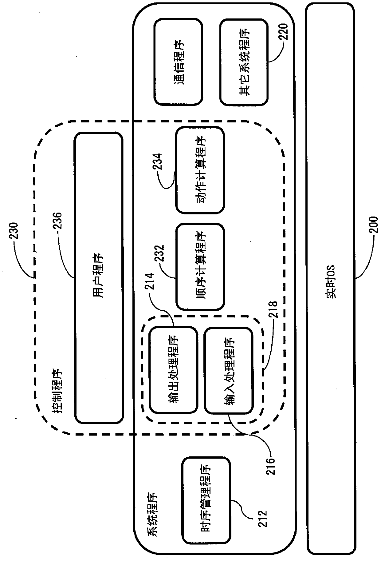
[0109] Figure 8 An example in which a plurality of cores execute the first control program and the second control program at a constant cycle is shown. The first control program and the second control program respectively include a first IO processing program, a second IO processing program, a first user program, a second user program, a first motion calculation program, and a second motion calculation program.

[0110] The sequence manager monitors the count value of the timer. If the specified period is reached, the timing management program causes the first core of the microprocessor to start executing the first control program. At the same time, the second core of the microprocessor is started to execute the second control program.

[0111] During the execution of the first control program, the first core of the microprocessor transmits the data used for communication with the communication buffer of the communication controller 150 from the communication buffer on the ...

no. 2 example >

[0125] Next, timings for starting execution of the first, second, and third control programs using the multi-core processor will be described.

[0126] Figure 9 It is a figure which shows the execution timing of the 1st - 3rd control program. The sequence management program starts executing the first control program and the second control program when it detects that the predetermined time has come. Put the third control program in the state of waiting for execution.

[0127] As shown in the figure, the IO of the first control program represents actions performed in accordance with the commands of the IO control program. The first core of the processor sends the output data and reads the input data according to the command of the first IO control program. (Because it is the same process as the above description, the description is omitted)

[0128] As shown in the figure, the UPG of the first control program indicates actions performed in accordance with the commands of t...


PUM


Abstract

Provided is a control apparatus (1) that can, by causing multiple control programs that include motion computation programs to be executed in parallel, shorten the execution cycle of control programs that are executed cyclically. A microprocessor (100) is configured to execute multiple control programs in parallel. When executing communication commands included in control programs that are to be executed in parallel, a scheduling program causes the microprocessor (100) to execute the communication commands such that there is no competition between communication processes in a communication controller (150).

Description

technical field [0001] The present invention relates to scheduling for executing a control program using a multi-core processor in a control device used to control the operation of machinery or equipment. Background technique [0002] Motion control for controlling the movement of motors is sometimes included as motion control for machinery, equipment, and the like. Such motion control is typically known as a programmable controller (programmable controller), which utilizes a CPU to execute a motion calculation program and sequence (sequence) calculations, and the motion calculation program is used to periodically control the output command value of the motor driver. [0003] For example, Patent Document 1 discloses that a programmable controller executes an operation calculation program to periodically output command values ​​to a motor driver for driving a motor. [0004] In Patent Document 1, a first control program (short-cycle operation program) and a second operation...

Claims


Application Information

Patent Timeline
Patent Type & Authority Patents(China)
IPC IPC(8): G05B19/042
CPCG05B19/0423G05B2219/34013G05B19/0421G05B19/4155G05B2219/2205G06F9/4887G05B2219/33273
Inventor 江口重行前川典弘田村嘉英西山佳秀
Owner ORMON CORP
Why Eureka
Try Eureka