Key structure

A key and keycap technology, applied in emergency connection, emergency contact form, tactile feedback, etc., can solve the problems of inability to adjust the speed of returning to the initial position, slow speed of returning to the initial position, and inability to conform to the trigger signal transmission path Direct and fast, the effect of increasing the trigger speed

Active Publication Date: 2016-10-12
DARFON ELECTRONICS (SUZHOU) CO LTD +1
View PDF5 Cites 12 Cited by
  • Summary
  • Abstract
  • Description
  • Claims
  • Application Information

AI Technical Summary

Problems solved by technology

[0004] However, computer users have various requirements for the feel of the keyboard. For example, some people require that the keycap return to the initial position as soon as possible after being pressed, while others require that the keycap return to the initial position after being pressed. slow the better
However, the speed at which the keycaps of the current keyboard return to the initial position after being pressed cannot be adjusted, so it cannot meet the requirements of all computer users.

Method used


Image

  • Key structure
  • Key structure
  • Key structure

Examples


no. 1 example

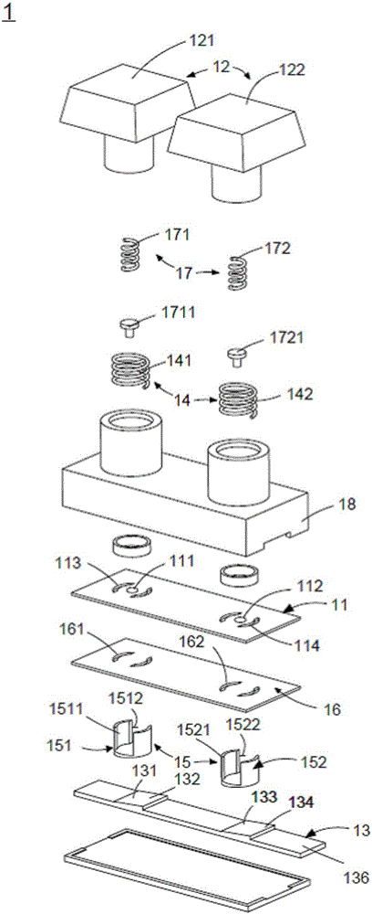
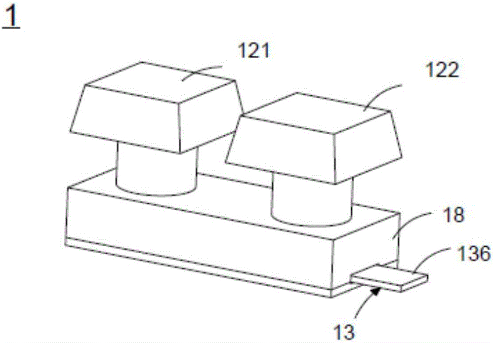
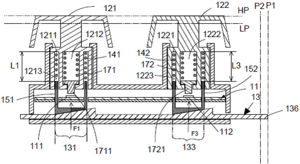
[0062] Please also refer to Figure 1 to Figure 3C , where, as figure 2 As shown, the keyboard 1 of the first embodiment has a circuit board 11, a keycap group 12, an adjustment member 13, a support elastic body group 14, a force transmission member group 15, a bearing plate 16, a trigger elastic body group 17 and a keyboard housing 18 . The force transmission component set 15 has a first force transmission component 151 and a second force transmission component 152 . The circuit board 11 is arranged on the carrier board 16, and the circuit board 11 has a first switch 111, a second switch 112, a pair of circuit board through holes 113 next to the first switch 111 and a pair of circuit board through holes next to the second switch 112. 114. The circuit board through-holes 113 and 114 are arc-shaped structures. Preferably, from a top view, the arc-shaped extension angle of the arc-shaped structures is less than 180 degrees. The carrier board 16 has a pair of carrier board t...

no. 2 example

[0073] Please also refer to Figure 4 ,like Figure 4 As shown, the biggest difference between the second embodiment and the first embodiment is that the keyboard of the second embodiment omits the setting of the trigger elastic body group, and directly forms it under the first keycap 121 and the second keycap 122 The touch structure triggers the first switch 111 and the second switch 112, so that the structure of the keyboard can be simplified and the manufacturing cost can be saved.

no. 3 example

[0075] Please also refer to Figure 5A to Figure 5B ,like Figure 5A As shown, the biggest difference between the third embodiment and the first embodiment is that in the keyboard of the third embodiment, the adjustment member 13 is arranged between the trigger elastic body group 17 and the circuit board 11, that is, the adjustment member 13 separates the trigger elastic body group 17 and the circuit board 11, thus the adjustment part 13 is formed with Figure 5B The through hole 137 shown can allow the first contact portion 1711 and the second contact portion 1721 to pass through, so as to achieve the purpose of triggering the first switch 111 and the second switch 112 .


PUM


Abstract

The invention discloses a key structure. The key structure comprises key caps, guiding mechanisms arranged on the key caps, actuating parts movably connected with the guiding mechanisms, circuit units, elastic parts and returning units. When a key cap is subjected to pressure, the key cap moves to a low position through a trigger position from a high position downwards. When the key cap moves to the trigger position, the corresponding circuit unit abuts against the corresponding actuating part to generate a trigger signal, and a preset length of the corresponding elastic part is maintained, so that relative motion between the corresponding actuating part and the key cap does not exist. When the key cap moves to the low position from the trigger position, the corresponding actuating part stops moving downwards, and the corresponding elastic part is compressed so as to enable the corresponding actuating part to move relative to the corresponding guiding mechanism. When the pressure is released, the corresponding elastic part and the corresponding returning unit provides elastic force and returning force respectively so as to enable the corresponding actuating part and the key cap to be returned to a position before the key cap is pressed. According to the key structure disclosed by the invention, the trigger signal is generated in a key stroke period so as to improve the trigger speed under the condition without influencing the key stroke, so that a trigger signal transmission path is more direct and quicker.

Description

technical field [0001] The invention relates to a button structure, more specifically, a button structure that can be triggered quickly without affecting the stroke of the button. Background technique [0002] A keyboard is a major tool for inputting commands into a computer and is widely used by computer users. A keyboard generally includes keycaps, a circuit board with switches, and an elastic body. When the keycap is pressed, the keycap will move downward from the initial position, compress the elastic body below, and trigger the switch of the circuit board. At this time, the elastic body will generate a restoring force due to the compression. When the pressing is released, the restoring force of the elastic body will act on the keycap, prompting the keycap to return to the initial position, and the next pressing can be performed. [0003] It should be noted that the speed at which the keycap returns to the initial position is directly proportional to the restoring forc...

Claims


Application Information

Patent Timeline
Patent Type & Authority Applications(China)
IPC IPC(8): H01H13/705H01H13/02
CPCH01H13/02H01H13/705H01H2207/03H01H2215/002H01H2221/036H01H2231/002
Inventor 张立德廖瑞铭颜志仲林坤德刘家宏
Owner DARFON ELECTRONICS (SUZHOU) CO LTD
Why Eureka
Try Eureka