
cable support

A support device and cable technology, applied in the field of supports, can solve the problems of large workload, high work intensity, and many cable supports for cable supports, and achieve the effects of reducing erection workload, labor intensity, and expanding support distance.

Active Publication Date: 2017-08-25
山东益客食品产业有限公司
View PDF6 Cites 0 Cited by
  • Summary
  • Abstract
  • Description
  • Claims
  • Application Information

AI Technical Summary

Problems solved by technology

Due to the large number of electrical equipment, the number of underground cables is also large. In the existing underground cable laying, most cables are supported by some simple brackets. Most of the existing cable brackets are fixed on the wall of the cable trench. And the distance between the two cable supports is short, because the length of the cable is longer, thereby causing the quantity of the cable support to be more, at the same time, the fixed workload of the cable support is not small, further, when constructing the cable, the cable needs to be used manually Hand lift it on the cable support. Because some cables are heavy, the workers lift the cables repeatedly, and the work intensity is also relatively high.

Method used


Image

  • cable support
  • cable support
  • cable support

Examples


Embodiment Construction

[0032] The following will combine specific embodiments and appendixes Figure 1-8 , clearly and completely describe the technical solutions in the embodiments of the present invention. Obviously, the described embodiments are only a part of the preferred embodiments of the present invention, rather than all the embodiments. Those skilled in the art can make similar modifications without departing from the connotation of the present invention, so the present invention is not limited by the specific embodiments disclosed below.

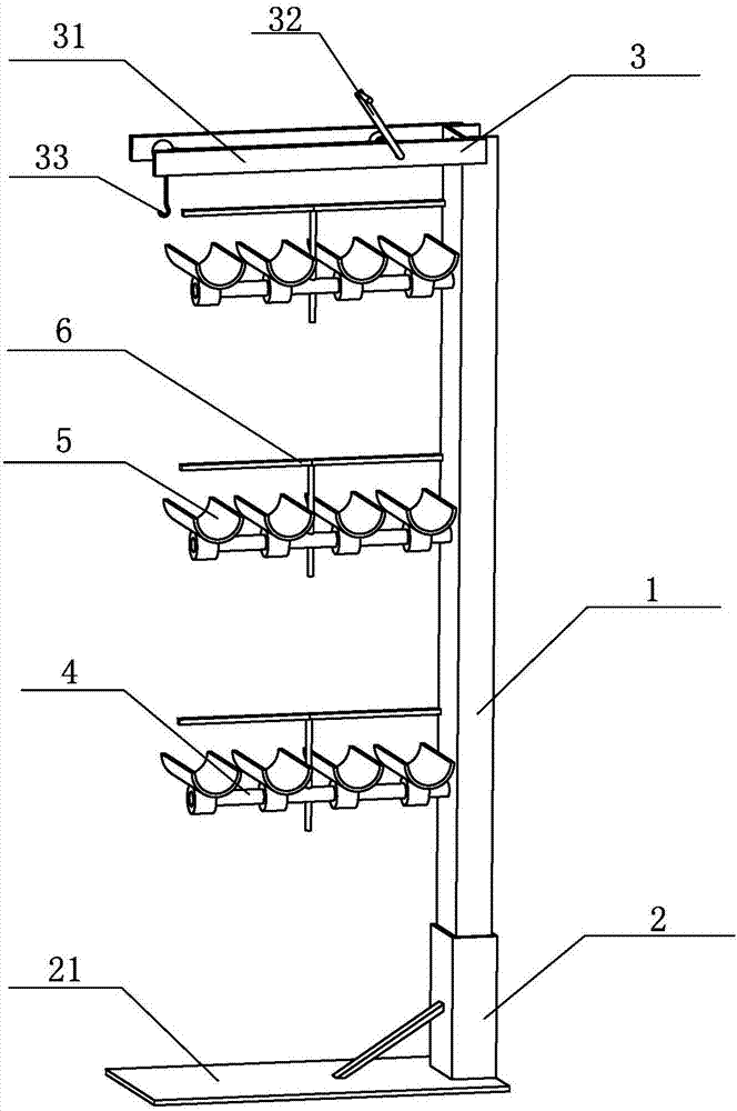
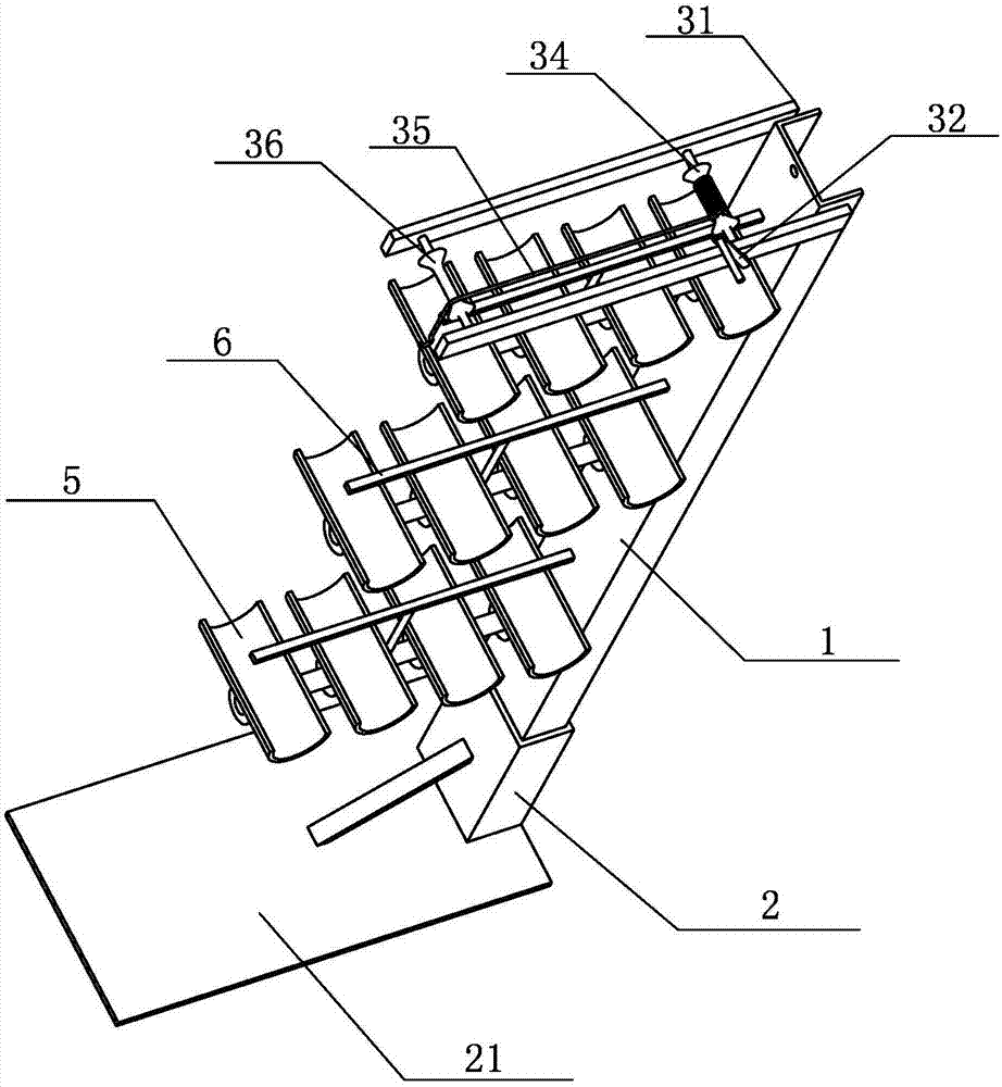
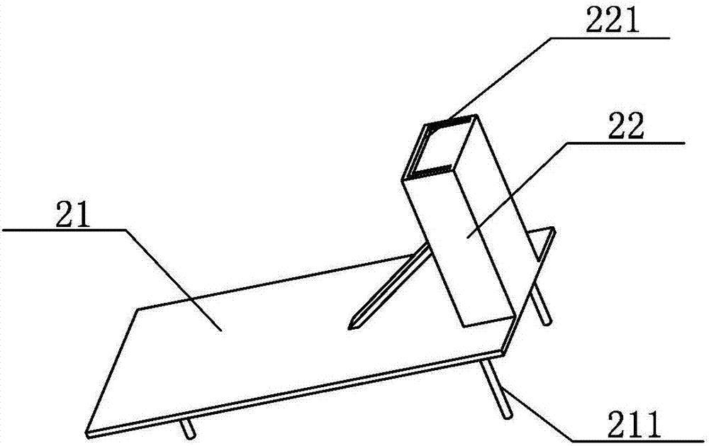
[0033] The present invention provides a cable support device (such as figure 1 shown), it includes a channel steel vertical rod 1, a support base 2 and a cable lifting device 3, and the support base 2 is located below the channel steel vertical rod 1. In order to facilitate the transportation of the entire device, the channel steel vertical rod 1 and the support base are connected. 2 is connected by plugging, the support base 2 includes a bottom plate ...


PUM


Abstract

The invention provides a cable supporting device comprising a channel-steel vertical rod, a support pedestal, and a cable lifting device. The support pedestal consists of a base plate and a plugging block arranged on the edge of the base plate; and a channel-steel groove matching the appearance of the channel-steel vertical rod is formed in the plugging block. The bottom of the channel-steel vertical rod is plugged in the channel-steel groove; at least one horizontal support rod is arranged at the back of the channel-steel vertical rod; a plurality of separation boards sleeve the horizontal support rod; and an auxiliary fixing device is arranged at the middle of the horizontal support rod. The cable lifting device is arranged at the top of the channel-steel vertical rod. The cable supporting device having a simple structure can be used conveniently; because the device does not need to be fixed on the wall, the preparation work of cable laying is reduced substantially; and with the lifting device, the cable can be lifted easily and can be placed at a corresponding erecting height, so that the labor intensity of the worker is reduced.

Description

technical field [0001] The invention relates to a bracket used in the field of power supply, in particular to a cable supporting device. Background technique [0002] With the continuous development of economy, the scale of some cities in our country is getting bigger and bigger. Due to the high density of urban residents and many tall buildings, in the power erection of prosperous cities, power supply cables are mainly laid underground. Due to the large number of electrical equipment, the number of underground cables is also large. In the existing underground cable laying, the cables are mostly supported by some simple brackets. Most of the existing cable brackets are fixed on the wall of the cable trench. And the distance between the two cable brackets is short, because the cable length is long, resulting in a large number of cable brackets, at the same time, the fixed workload of the cable bracket is not small, further, when constructing the cable, the cable needs to be ...

Claims


Application Information

Patent Timeline
Patent Type & Authority Patents(China)
IPC IPC(8): H02G3/04
CPCH02G3/0456
Inventor 温鲁平李茂林李瑜庄力行张健万旭胥超刘华博
Owner 山东益客食品产业有限公司
Learn More