Micro-grid system monitoring method having reactive automatic compensation function

A technology of automatic power compensation and micro-grid, applied in reactive power compensation, reactive power adjustment/elimination/compensation, wind power generation, etc., can solve problems such as weak grid, over-limit bus voltage, large fluctuation range, etc.

Inactive Publication Date: 2016-10-12
CHENGDU XINWEIBAO TECH CO LTD
View PDF3 Cites 13 Cited by
  • Summary
  • Abstract
  • Description
  • Claims
  • Application Information

AI Technical Summary

Problems solved by technology

[0004] The microgrid composed of wind power has intermittent and strong randomness in its output. The change of wind power output will affect the reactive power distribution of the transmission channel, and then change the bus voltage of the channel. The overall performance is that with the change of wind power output, the AC output channel At the same time, because most of the wind power is connected to remote areas, the grid frame of the outgoing channel is relatively weak, and the short-circuit capacity is small, so the voltage fluctuation will be "amplified", the fluctuation range is large, and even the busbar Operating risks such as voltage over-limit, and the problem of difficult voltage control after large-scale wind power access will be highlighted

Method used


Image

  • Micro-grid system monitoring method having reactive automatic compensation function
  • Micro-grid system monitoring method having reactive automatic compensation function
  • Micro-grid system monitoring method having reactive automatic compensation function

Examples


Embodiment Construction

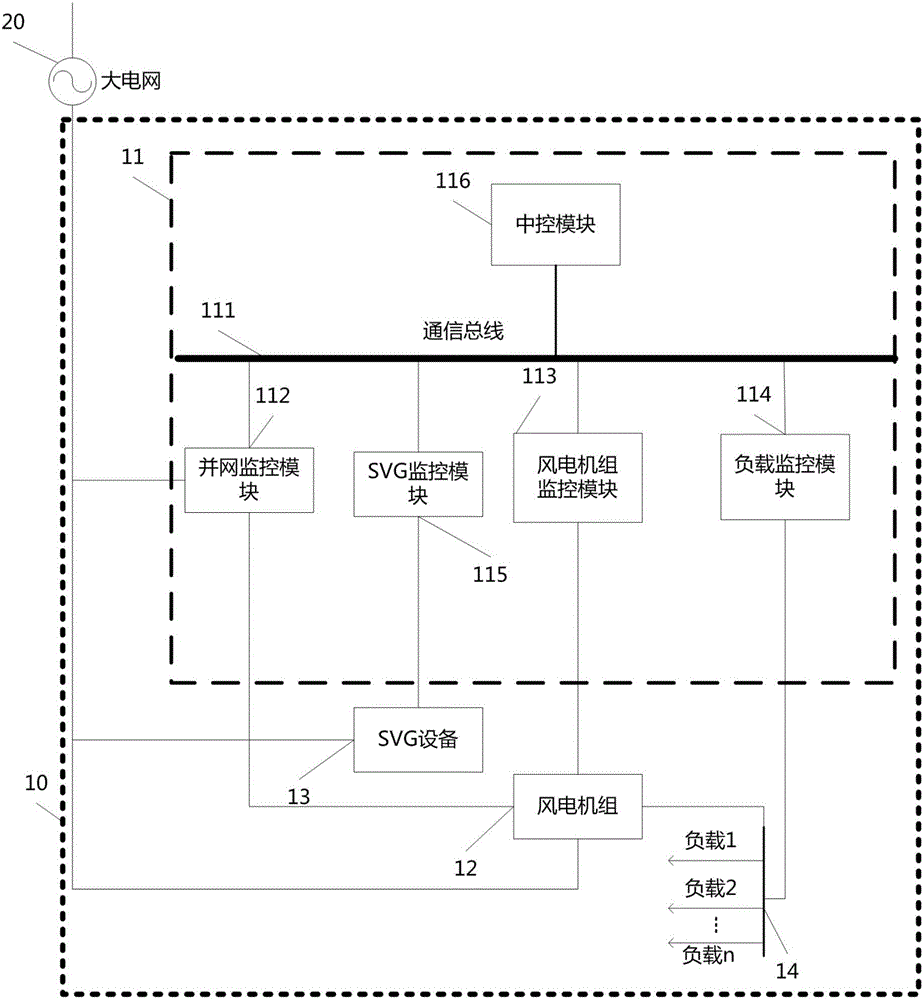
[0084] figure 1 It shows a micro-grid system 10 with automatic reactive power compensation of the present invention. The micro-grid 10 includes: a wind turbine 12, a load 14 in the micro-grid, an SVG device 13, and a monitoring device 11; the monitoring device 11 includes: The wind turbine monitoring module 113 is used to monitor the wind turbine 12 in real time, predict the generated power of the wind turbine 12, and control the operation of the wind turbine; the grid-connected monitoring module 112 is used to monitor the AC bus voltage of the grid-connected point and control The grid-connected operation of the microgrid 10; the load monitoring module 114 is used to monitor the load 14 in the microgrid in real time; the SVG monitoring module 115 is used to monitor the SVG device 13 in real time; the central control module 116 is used to determine the operation of the microgrid 10 method, and send instructions to each module in the monitoring device 11 to execute the operation...


PUM


Abstract

The invention discloses a micro-grid system monitoring method having a reactive automatic compensation function. The method includes steps of S1, obtaining a wind power unit operation data in real time and storing data by a wind power unit monitoring unit, obtaining micro-grid inner load power demand condition in real time, and performing prediction on output active power and reactive power of a wind power unit in a future predetermined moment according to the operation data of the wind power unit; S2, collecting grid connecting point voltage information and determining micro-grid active and reactive output demand according to large-grid scheduling commands at the same time; S3, realizing reactive optimization operation of the micro-grid by taking the micro-grid active and reactive output demand, current micro-grid inner load power demand, wind power unit output active and reactive power, SVG device output reactive power as constraint conditions and inhibiting voltage fluctuation. The method can predicate power generation power of the wind power unit in the micro-grid and load change of the micro-grid. By the combination with a multi-target optimization reactive power distribution method having active loss influence in the micro-grid under a wind power unit constant active power control mode, economical operation of the micro-grid is improved, participation of bulk power grid voltage adjustment of the micro-grid according to requirements of a bulk power grid during grid connection is ensured and voltage stability during grid-connected operation is guaranteed.

Description

Technical field [0001] The invention relates to a monitoring method of a micro-grid system with automatic reactive power compensation. Background technique [0002] The energy and environmental crisis has become an important issue affecting the sustainable development of human beings, and the utilization of clean and renewable energy is the fundamental way to solve this problem. With the maturity of wind power generation, photovoltaic power generation, wave power generation and other renewable energy power generation technologies, more and more renewable energy microgrids are connected to the power grid in a distributed manner to meet people's daily production and living electricity needs. [0003] Especially for wind power, several million-kilowatt wind power bases in my country have been completed and connected to the grid for operation, and the planned eight million-kilowatt wind power bases are also being gradually constructed. The development mode of wind power in my co...

Claims


Application Information

Patent Timeline
Patent Type & Authority Applications(China)
IPC IPC(8): H02J3/16H02J3/50H02J3/18
CPCH02J3/16H02J3/1835H02J3/50Y02E10/76Y02E40/30
Inventor 靖新宇
Owner CHENGDU XINWEIBAO TECH CO LTD
Why Eureka
Try Eureka