LED energy-saving driving system

A drive system and frequency adjustment technology, applied in electrical components, electroluminescent light sources, lighting devices, etc., can solve problems such as inability to meet energy-saving requirements and high power consumption, and achieve the effect of reducing startup power consumption and small startup current

Inactive Publication Date: 2016-10-12
CHENGDU SINOMETALLURGY ENERGY CONSERVATION ENVIRONMENTAL PROTECTION ENG CO LTD
View PDF0 Cites 0 Cited by
  • Summary
  • Abstract
  • Description
  • Claims
  • Application Information

AI Technical Summary

Problems solved by technology

However, the traditional LED drive system consumes a lot of po

Method used


Image

  • LED energy-saving driving system

Examples


Embodiment

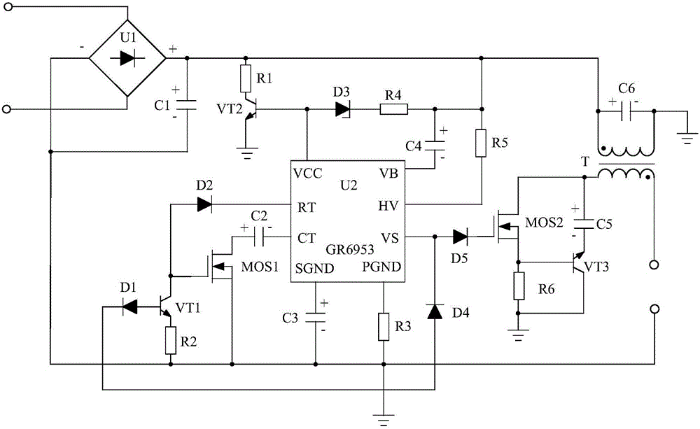
[0014] Such as figure 1 As shown, the present invention is mainly composed of the control chip U2, the transformer T, the power supply circuit and the frequency adjustment circuit connected to the control chip U2 respectively, the P pole is connected with the frequency adjustment circuit, and the N pole is connected with the VS pin of the control chip U2 Diode D4, the anode is connected to the SGND pin of the control chip U2, and the negative pole is connected to the frequency adjustment circuit. Capacitor C3, one end is connected to the PGND pin of the control chip U2, and the other end is connected to the frequency adjustment circuit while grounding The resistor R3 is connected in series to the gate drive circuit between the VS pin of the control chip U2 and the non-identical end of the secondary inductance coil of the transformer T, and the positive pole is connected to the same-name end of the primary inductance coil of the transformer T, The negative electrode is connecte...


PUM


Abstract

The invention discloses an LED energy-saving driving system. The LED energy-saving driving system is characterized by manly consisting of a transformer T, a control chip U2, a power supply circuit and a frequency adjustment circuit which are connected with the control chip U2, a diode D4 which has a P electrode connected with the frequency adjustment circuit and an N electrode connected with a VS pin of the control chip U2, and the like. The system, by use of a GR6953 integrated chip as a control chip and through combination with a peripheral circuit, forms a half-bridge control structure, such that starting power consumption is reduced, and the system is more energy-saving.

Description

technical field [0001] The invention relates to a drive system, in particular to an LED energy-saving drive system. Background technique [0002] At present, due to the characteristics of low energy consumption, long service life, safety and environmental protection, LED lamps have become one of the mainstream products for people's living lighting. With the continuous improvement of people's awareness of energy saving, people's energy consumption requirements for LED drive systems are also getting higher and higher, which brings new challenges to LED drive systems. However, the traditional LED drive system consumes a lot of power when it is started, which cannot meet people's energy-saving needs. Contents of the invention [0003] The object of the present invention is to solve the defect of large power consumption during start-up of the current LED drive system, and provide an LED energy-saving drive system. [0004] The purpose of the present invention is achieved thro...

Claims


Application Information

Patent Timeline
IPC IPC(8): H05B33/08H05B44/00H05B45/30
CPCH05B45/00Y02B20/30
Inventor 不公告发明人
Owner CHENGDU SINOMETALLURGY ENERGY CONSERVATION ENVIRONMENTAL PROTECTION ENG CO LTD
Why Eureka
Try Eureka