
Heat dissipation device

A heat dissipation device and thermal energy technology, applied in the direction of cooling/ventilation/heating transformation, electrical components, electrical equipment construction parts, etc., can solve the problem of affecting the use efficiency of functional electrical components, the inability to simplify and intuitive operation methods, and the dependence of mobile terminal systems Large and other problems, to achieve the effect of saving indoor layout space, effective heat dissipation, and effective discharge

Active Publication Date: 2016-10-12
HANGZHOUSNGOOSE ELECTRICAL
View PDF5 Cites 6 Cited by
  • Summary
  • Abstract
  • Description
  • Claims
  • Application Information

AI Technical Summary

Problems solved by technology

[0002] Home digital systems are being researched and promoted more and more widely. Most of them are operated together by intelligent digital devices together with software or computer programs. For example, in order to realize centralized control of home products, users usually choose to use mobile terminals ( Such as mobile phones or personal computers, etc.) to control, but this method is limited by the functionality of the mobile terminal itself, and the complicated installation of firmware cannot make the user's operation method simplified and intuitive, and at the same time, it is aimed at the functions of each household product. The control instruction set is highly dependent on the mobile terminal system, which greatly limits the update method of household products
[0003] In addition, the compact structure realized in order to solve such defects often has the problem of poor heat dissipation, which will greatly affect the use efficiency of various functional electrical components inside the structure

Method used


Image

  • Heat dissipation device
  • Heat dissipation device
  • Heat dissipation device

Examples


Embodiment Construction

[0035] Reference in this specification to "one embodiment" or "example" means that a particular feature, structure, or characteristic described in connection with the embodiment can be included in at least one embodiment of the present disclosure. The appearances of the phrase "in one embodiment" in various places in the specification are not necessarily all referring to the same embodiment.

[0036] In addition, in the accompanying specification and claims of the present invention, the terms "coupled" and "coupled" and their derivatives may be used. Those of skill should understand that these terms are not intended as synonyms for each other. "Coupled" is used to indicate that two or more elements, which may or may not be in direct physical or electrical contact with each other, co-operate or interact with each other. "Connected" is used to mean the establishment of communication between two or more elements coupled to each other.

[0037] The processing steps shown in the ...


PUM


Abstract

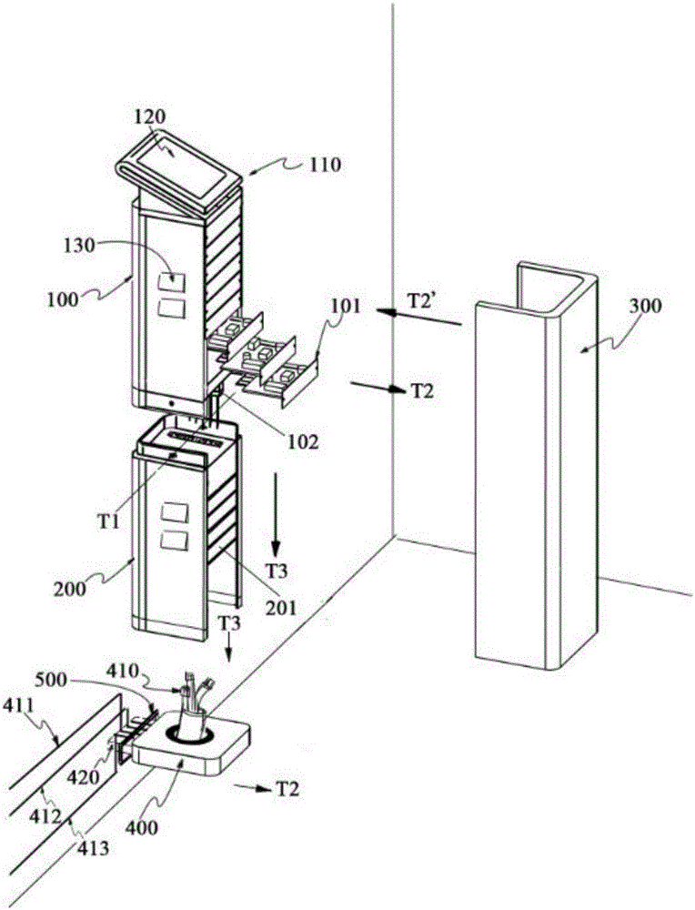
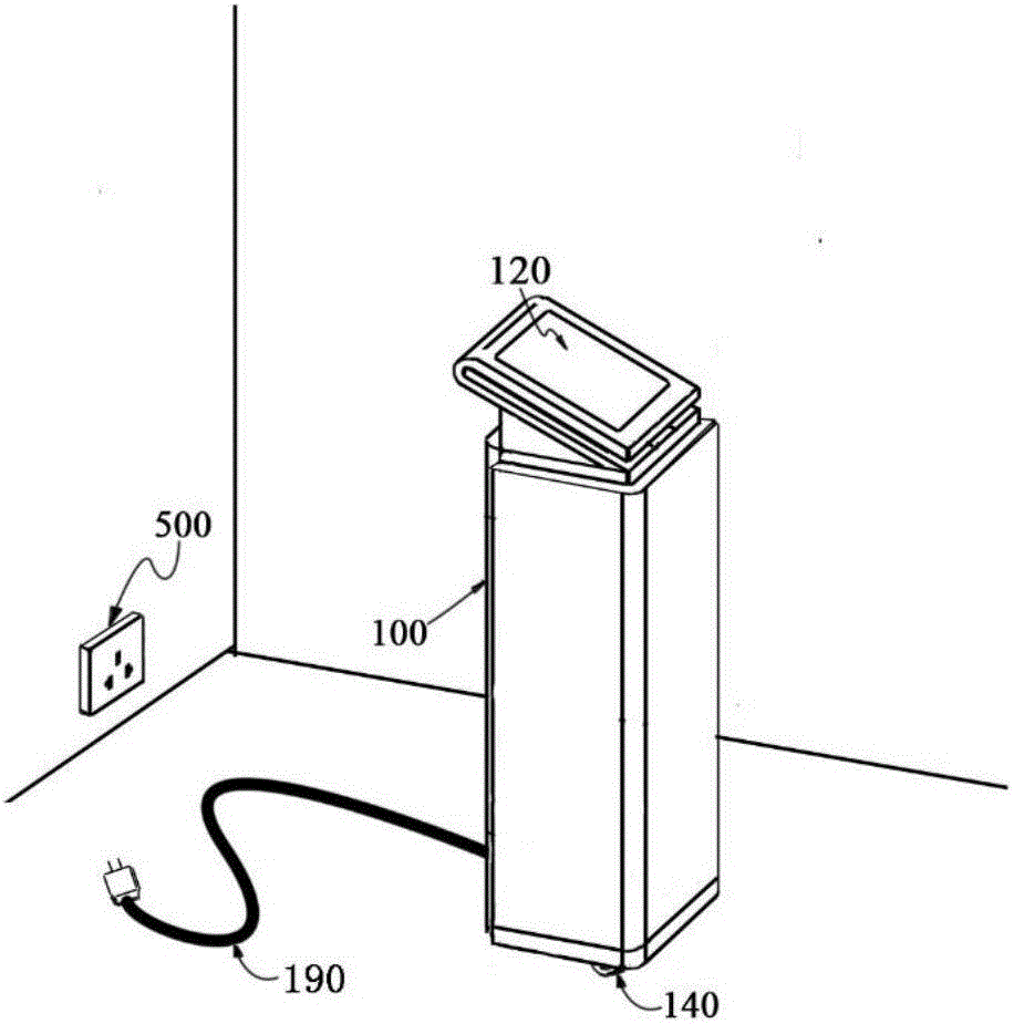
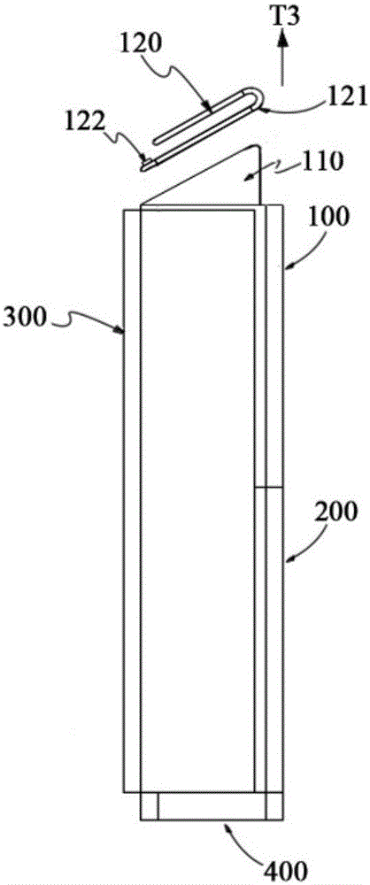
The invention discloses a heat dissipation device. The heat dissipation device comprises a plurality of bodies installed in a stacked manner, a pedestal used for bearing the bodies and installing the bodies in a building surface, the pedestal comprises an input end connected with a home external transmission network and an output end connected with a home internal transmission network, the bodies comprise a first body, the first body is fixedly installed on the pedestal, a flow guide plate can be arranged in a bottom part empty cavity of the first body, a plurality of flow guide components are arranged on the flow guide plate, and the flow guide components are used for extracting a gas from the bottom part empty cavity to an accommodating cavity inside the first body and diffusing the gas towards the top part of the accommodating cavity.

Description

technical field [0001] The invention mainly relates to a smart home system, in particular to a heat dissipation device for a home digital switching device. Background technique [0002] Home digital systems are being researched and promoted more and more widely. Most of them are operated together by intelligent digital devices together with software or computer programs. For example, in order to realize centralized control of home products, users usually choose to use mobile terminals ( For example, mobile phones or personal computers, etc.) to control, but this method is limited by the functionality of the mobile terminal itself, and the complicated installation of firmware cannot make the user's operation mode simplified and intuitive, and at the same time, it is aimed at the functions of each household product. The control instruction set is highly dependent on the mobile terminal system, which greatly restricts the update method of household products. [0003] In additi...

Claims


Application Information

Patent Timeline
Patent Type & Authority Applications(China)
IPC IPC(8): H05K7/20
CPCH05K7/20145
Inventor 章昭徐鹤还王晓东
Owner HANGZHOUSNGOOSE ELECTRICAL
Learn More