Engine cooling liquid automatic supplying and recycling system

A technology of engine coolant and recovery system, applied in engine cooling, engine components, machine/engine, etc., can solve the problems of high coolant temperature, high heat load of parts, and low degree of automation.

Active Publication Date: 2016-11-30
HENAN DIESEL ENGINE IND
View PDF7 Cites 5 Cited by
  • Summary
  • Abstract
  • Description
  • Claims
  • Application Information

AI Technical Summary

Problems solved by technology

[0003] Coolant has cooling, anti-corrosion, anti-rust and anti-freezing functions for the engine. During use, the loss of coolant will be caused by evaporation and leakage. If the coolant temperature is too high, it will cause engine cavitation in severe cases, and the thermal load of parts will be too high, which will reduce the service life of the engine; when the coolant of the generator set is replenished manually, it will be affected by the liquid level alarm and on-site inspection, which is highly dependent on the on-site personnel. The degree of automation is not high; if there is a low liquid level alarm failure or the on-site inspection does not find that the coolant is insufficient in time, it is easy to cause the coolant to be replenished in time, which will have a greater impact on the power station with multiple units; Trouble, when the generator set is overhauled, maintained or removed, the coolant is released directly, which not only causes waste, but also pollutes the environment
[0004] The existing related patents (application numbers: 201310274300.4 and 201520870390.8) all involve coolant supply and recovery with the following characteristics: (1) The pipeline of the supply system is complex, occupies a large area, and is not suitable for power plants with multiple gas generating units; (2) The old and new coolants in the recovery system are mixed and stored, polluting the fresh coolant, and need to be blown by high-pressure airflow, which makes the system complex; (3) The redundant design is not enough and the reliability is not high; (4) There are limitations in the use in severe cold areas

Method used


Image

  • Engine cooling liquid automatic supplying and recycling system

Examples


Embodiment Construction

[0014] The present invention is described in conjunction with accompanying drawing and specific implementation case:

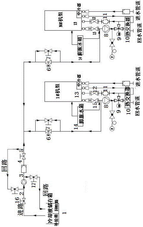
[0015] Such as figure 1 As shown, an engine coolant automatic replenishment and recovery system, the engine coolant automatic supply and recovery system has a coolant storage tank 1 for replenishing and recovering the coolant for the generator set; the coolant storage tank 1 It includes a supply tank and a recovery tank; the outlet of the supply tank of the coolant storage tank 1 is respectively connected to the automatic supply and recovery branch of each generator set through a manual ball valve I2, an electric pump I3, a filter 4, and a manual ball valve II5 pass; the automatic supply recovery branch has a manual ball valve III7 and an explosion-proof solenoid valve 6 connected in series with the manual ball valve II5, and the manual ball valve III7 is connected in parallel with the explosion-proof solenoid valve 6; the automatic supply recovery branch road...


PUM


Abstract

The invention belongs to the technical field of generator sets, and particularly relates to an engine cooling liquid automatic supplying and recycling system. The system comprises a cooling liquid storage box (1) for supplying and recycling cooling liquid for generator sets. The cooling liquid storage box (1) comprises a supplying box and a recycling box. The outlet of the supplying box is communicated with an automatic supplying and recycling branch through a manual ball valve I (2), an electric pump I (3), a filter (4) and a manual ball valve II (5). The water return opening of the generator set (13) is communicated with the recycling box through a stop valve II (15), a manual ball valve III (7), a manual ball valve IV (16), an electric pump I (3) and a manual ball valve V (17). An expansion water tank (14) for supplying cooling liquid to the generator set in real time is arranged one each generator set. Concentration processing or secondary utilizing is achieved, and resource waste and environment pollution are avoided.

Description

[0001] Technology area [0002] The invention belongs to the technical field of generator sets, and in particular relates to an automatic replenishment and recovery system for engine coolant. Background technique [0003] Coolant has cooling, anti-corrosion, anti-rust and anti-freezing functions for the engine. During use, the loss of coolant will be caused by evaporation and leakage. If the coolant temperature is too high, it will cause engine cavitation in severe cases, and the thermal load of parts will be too high, which will reduce the service life of the engine; when the coolant of the generator set is replenished manually, it will be affected by the liquid level alarm and on-site inspection, which is highly dependent on the on-site personnel. The degree of automation is not high; if there is a low liquid level alarm failure or the on-site inspection does not find that the coolant is insufficient in time, it is easy to cause the coolant to be replenished in time, which w...

Claims


Application Information

Patent Timeline
Patent Type & Authority Applications(China)
IPC IPC(8): F01P11/00
CPCF01P11/00
Inventor 黄超伟任晓辉李文彬彭阳
Owner HENAN DIESEL ENGINE IND
Why Eureka
Try Eureka