Blind rivet arrangement and joint

A blind rivet, rivet head technology, applied in the direction of rivets, screws, connecting components, etc., can solve problems such as rotational symmetry deviation, and achieve the effect of achieving retention force, realizing cost saving, good centering or guiding

Inactive Publication Date: 2016-10-12
NEWFREY
View PDF8 Cites 2 Cited by
  • Summary
  • Abstract
  • Description
  • Claims
  • Application Information

AI Technical Summary

Problems solved by technology

When deforming the rivet shank, this can lead to deviations in rotational symmetry and thus to misalignment of setting blind rivets

Method used


Image

  • Blind rivet arrangement and joint
  • Blind rivet arrangement and joint
  • Blind rivet arrangement and joint

Examples


Embodiment Construction

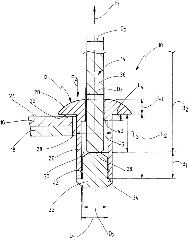
[0059] figure 1 A schematic view in longitudinal section of a first embodiment of a blind rivet arrangement according to the invention is shown, generally designated by the reference numeral 10 .

[0060] The blind rivet set 10 includes a rivet body 12 and a rivet mandrel 14 . The blind rivet arrangement 10 may be used to join a workpiece arrangement comprising at least one first workpiece 16 (visible side workpiece) and one second workpiece 18 (blind side workpiece).

[0061] The rivet body 12 comprises a rivet head 20 in known manner comprising a contact face 22 to abut against a top surface 24 of the visible side workpiece 16 . The rivet head 20 is joined to a rivet shank 26 which may be inserted into a workpiece hole 28 in the workpiece arrangement. The rivet body 12 is penetrated by an axially continuous rivet hole 30 .

[0062] The mandrel 14 includes a mandrel head 32 realized for abutting against an end surface 34 of the rivet shank 26 . Furthermore, the mandrel 14...


PUM


Abstract

Blind rivet arrangement (10) for producing a blind rivet joint (64), said blind rivet arrangement having a rivet body (12) and having a mandrel (14), wherein the rivet body (12) comprises a rivet head (20), a rivet shank (26) and a continuous rivet bore (30), wherein the mandrel (14) comprises a mandrel head (32) and a mandrel shank (36) which is inserted in the rivet bore, wherein the rivet bore (30) comprises a first bore cross section (D1) in the region of an end of the rivet shank (26) which is opposite the rivet head (20), wherein the mandrel shank(36) comprises a first shank cross section (D2) in a first mandrel region (B1) adjacent to the mandrel head (32), and wherein the first shank cross section (D2) is adapted to the first bore cross section (D1). In this case, in a second mandrel region (B2) which projects out of the rivet bore (30), the mandrel shank (36) comprises a second shank cross section (D3) which is smaller than the first shank cross section (D2).

Description

technical field [0001] The present invention relates to a blind rivet device for forming blind rivet joints, said blind rivet device having a rivet body and having a mandrel, wherein said rivet body comprises a rivet head, a rivet shaft and a continuous rivet hole, wherein said the mandrel comprises a mandrel head and a mandrel shaft inserted into the rivet hole, wherein the rivet hole comprises a first hole section in the region of the end of the rivet shank opposite the rivet head, and wherein The mandrel rod includes a first rod section in a first mandrel region adjacent the mandrel head. [0002] Furthermore, the invention relates to a blind rivet joint having at least two workpieces and having a shaped blind rivet arrangement of the type described above. Background technique [0003] A blind rivet device of this type is known from document WO 2009 / 098431 A1 and is used for joining workpieces, with access only possible from one side (visible side). In this case, the bl...

Claims


Application Information

Patent Timeline
Patent Type & Authority Applications(China)
IPC IPC(8): F16B19/10
CPCF16B19/1054
Inventor O.卢茨S.施耐德H.鲍曼M.威斯林
Owner NEWFREY
Why Eureka
Try Eureka