

Power demand control device, power demand control method, power demand control system, program, and recording medium
A technology for power demand control and determination device, applied in general control systems, control/regulation systems, power network operating system integration, etc., can solve problems such as inability to set selection criteria, power consumption fluctuations, etc., to alleviate the reduction of production efficiency Effect
- Summary
- Abstract
- Description
- Claims
- Application Information
AI Technical Summary
Problems solved by technology
Method used
Image

Examples
Embodiment approach 1
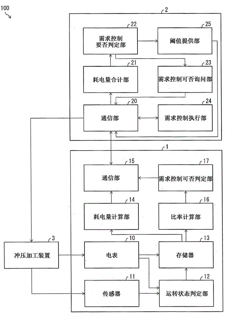
[0081] The following is based on Figure 1 to Figure 4 A first embodiment of the present invention will be described.
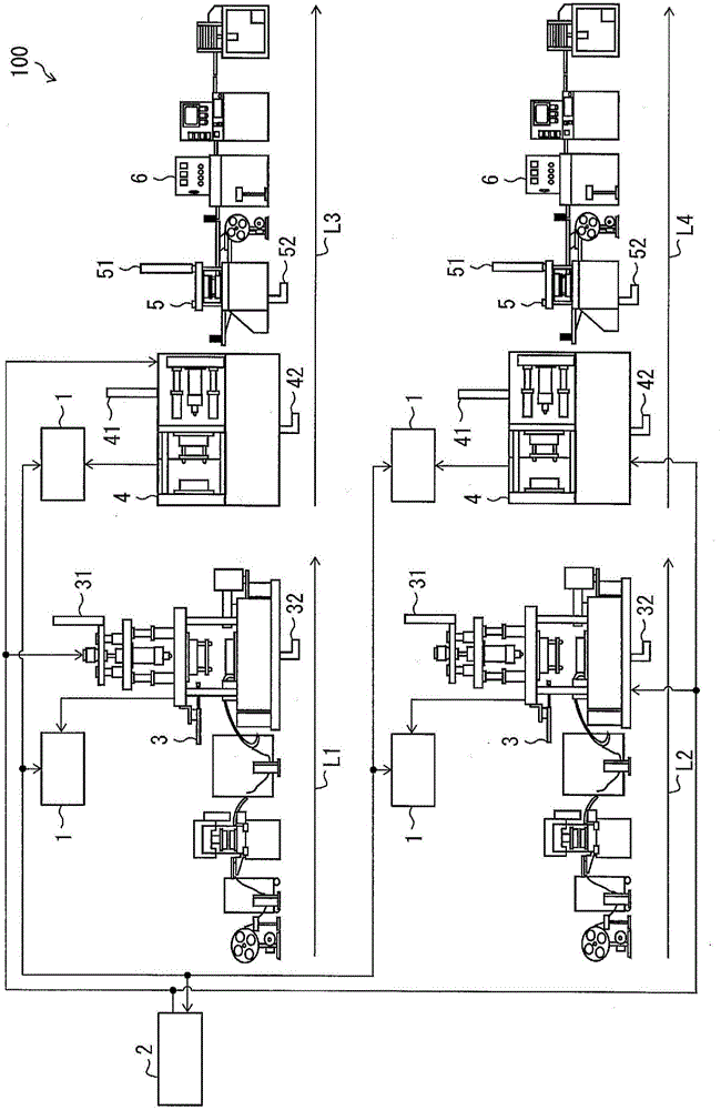
[0082] First, refer to the following figure 2 , the configurations of the production lines L1 to L4 and the power demand control system 100 according to the present embodiment will be described. figure 2 It is a figure which shows the structure of the production line L1-L4 of 1st Embodiment of this invention, and the structure of the electric power demand control system 100.
[0083] The production lines L1 to L4 shown in the figure are production facilities for disposing various production devices (apparatus) for automatically producing predetermined products. The production lines L1 to L4 are installed in the same facility (workshop).
[0084] The production lines L1 and L3 include a press processing device 3 . The press working device 3 presses metal parts such as electrode terminals required for the product. The products processed in the line L1 or...
no. 2 Embodiment approach
[0152] Next, a second embodiment of the present invention will be described. In addition, the same reference numerals are assigned to the components common to those in Embodiment 1, and detailed description thereof will be omitted.
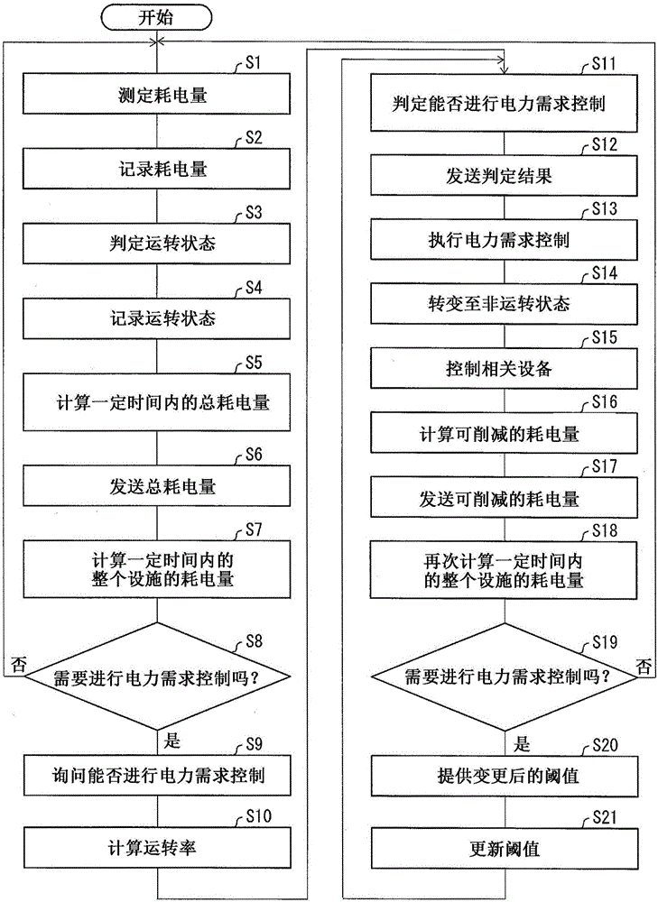
[0153] In the present embodiment, the power controller 1 calculates the energy generated by the power demand control of the production line based on the temporal change of the non-operating state of the press processing device 3 recorded in the memory 13 after the production line L1 transitions to the non-operating state. Loss production quantity. The number of products produced per unit time in the production line is determined in advance in the power controller 1 as the production takt. Here, the power controller 1 multiplies the production tact by the duration (total time) of the non-operating state of the production line after the power demand control, thereby calculating the quantity of defective production generated during the duration. As...
no. 3 Embodiment approach
[0155] The following is based on Figure 5 A third embodiment of the present invention will be described. In addition, the same code|symbol is attached|subjected to each part common to the said 1st or 2nd embodiment, and detailed description is abbreviate|omitted.
[0156] Figure 5 It is a figure which shows the structure of the electric power demand control system 100 which concerns on 3rd Embodiment of this invention. The configuration of the power demand control system 100 of the present embodiment is the same as that of the power demand control system 100 of the first embodiment. However, the object of power demand control is different. In the present embodiment, the power demand control system 100 makes the air-conditioning equipment (apparatus) in the workshop an object of power demand control.
[0157] Such as Figure 5 As shown, there are 2 air-conditioning internal units 7 and 3 air-conditioning external units 8 in the workshop. The air-conditioning internal un...
PUM
 Abstract
Description
Claims
Application Information