Bolt connection joint for eccentric beam column and assembling method

A technology for connecting nodes and beams and columns, which is applied in the direction of construction and building construction, can solve the problems of large welding residual stress, large amount of materials, and hindrance to the installation of wall panels, and achieve the effect of eliminating the concentration of triaxial stress

Active Publication Date: 2016-10-19
XI'AN UNIVERSITY OF ARCHITECTURE AND TECHNOLOGY
View PDF7 Cites 0 Cited by
  • Summary
  • Abstract
  • Description
  • Claims
  • Application Information

AI Technical Summary

Problems solved by technology

Because when the side length is small, it is not only difficult to weld, but also hinders the concrete pouring in the pipe. In addition, the beam flange and the inner partition plate penetrate the weld on both sides of the same column wall, and the steel produces a large welding residual stress, which makes the steel at the joint easy to produce delamination or brittle failure
[0005] (2) Affect the appearance and use of buildings
And when applied to corner columns, the horizontal ring plate not only hinders the installation of wall panels, but also causes the reinforcement ring to protrude from the building facade, causing convex corners at the indoor and outdoor joints, which affects the look and feel, which needs to be solved by decoration or ceiling
[0006] (3) The mechanical properties of joints and the simplicity and economy of construction cannot be both
In practical applications, some types of joints have better mechanical properties, and the overall stiffness of the joints is also good, but the amount of materials is large and the construction is complicated

Method used


Image

  • Bolt connection joint for eccentric beam column and assembling method
  • Bolt connection joint for eccentric beam column and assembling method
  • Bolt connection joint for eccentric beam column and assembling method

Examples


Embodiment Construction

[0035] Below in conjunction with accompanying drawing, the embodiment of the present invention is described in detail: present embodiment implements under the premise of the technical scheme of the present invention, has provided detailed implementation mode and concrete operation process, but protection scope of the present invention is not limited to the following the embodiment.

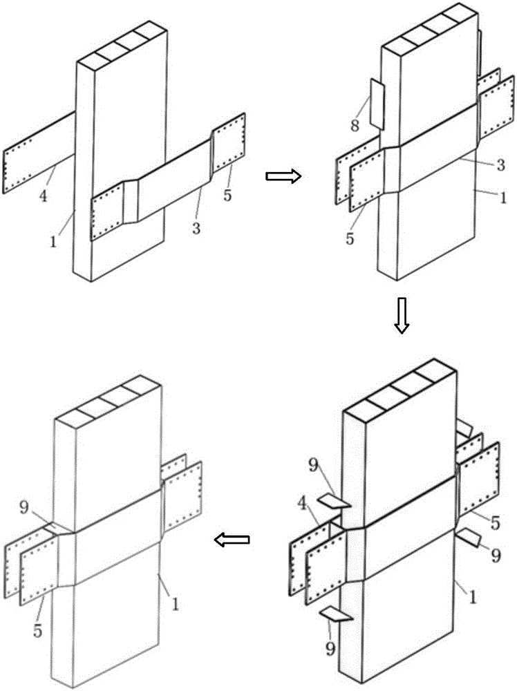
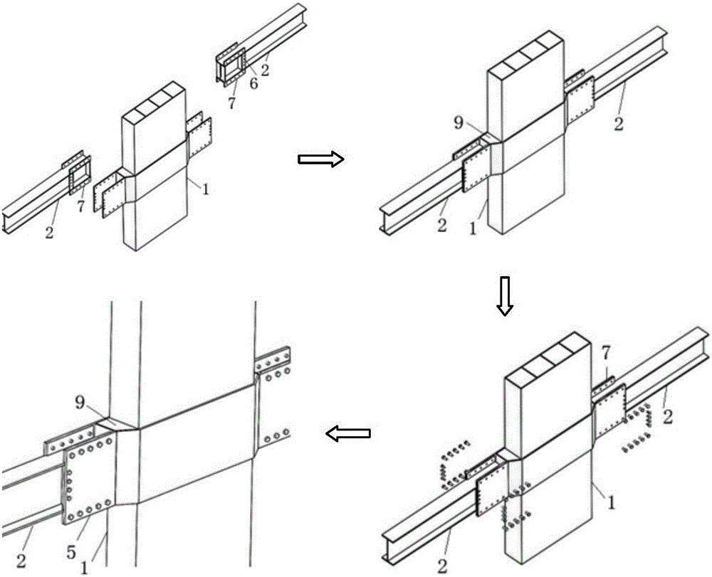
[0036] see image 3 , the present invention includes a first steel plate 3 and a second steel plate 4 welded on both sides of the multi-cavity steel pipe concrete composite column, that is, two steel plates are arranged on both sides of the multi-cavity steel pipe concrete composite column, and the first steel plate 3 includes a first section The steel plate, the second steel plate, the third steel plate and the fourth steel plate 5, the first steel plate and the third steel plate are symmetrically arranged on both sides of the second steel plate, and the first steel plate and the third steel plat...


PUM


Abstract

The invention discloses a bolt connection joint for an eccentric beam column and an assembling method. The bolt connection joint comprises a first steel plate and a second steel plate which are arranged on the two sides of a multi-cavity steel pipe concrete combined column. The first steel plate comprises a first steel plate section, a second steel plate section, a third steel plate section and a fourth steel plate section. The first steel plate section and the third steel plate section are symmetrically arranged on the two sides of the second steel plate section in an inclined mode. The second steel plate section is parallel to the second steel plate. The end of the first steel plate section and the end of the third steel plate section are each provided with a fourth steel plate section parallel to the second steel plate section. The top flange and the bottom flange of a steel beam are each provided with a lug plate connected with the fourth steel plate section. The two sides of a web plate of the steel beam are symmetrically provided with connection angles. The joint is high in assembled degree, the multi-cavity steel pipe concrete combined column, the steel plates, the steel beam, the lug plates and the connection angles can be prefabricated in factories, the welding workload of installation is reduced, and only positioning assembly is needed during on-site installation. The joint is simple in form, high in assembled degree and convenient and fast to install.

Description

technical field [0001] The invention relates to a multi-cavity steel pipe concrete composite column structure system in the technical field of construction engineering, in particular to a bolt connection node and an assembly method for eccentric beam columns. Background technique [0002] The multi-cavity steel pipe concrete composite column composite structure system is a new type of steel pipe concrete composite column structure system that solves the problem of protruding column feet in residential systems. It has the advantages of high bearing capacity, good plasticity and toughness, and convenient construction. [0003] At present, my country's "Technical Regulations for Rectangular Concrete-filled Steel Tube Structures" (GECS159: 2004) provides steel-beam joints for concrete-filled steel tube composite columns, which mainly include inner diaphragm type and outer ring plate type. But so far, there are the following deficiencies in the connection between the steel pipe ...

Claims


Application Information

Patent Timeline
Patent Type & Authority Applications(China)
IPC IPC(8): E04B1/30E04B1/58
CPCE04B1/30E04B1/58E04B2001/5875
Inventor 郝际平陈永昌薛强孙晓岭樊春雷刘斌黄育琪王磊刘瀚超何梦楠尹伟康赵子健张峻铭
Owner XI'AN UNIVERSITY OF ARCHITECTURE AND TECHNOLOGY
Why Eureka
Try Eureka