A battery pack control unit, control system and control method

A technology for controlling units and battery packs, applied in electrical components, battery circuit devices, current collectors, etc., can solve problems such as high complexity, reduced reliability of single cells, and difficulty in implementation.

Active Publication Date: 2018-10-23
深圳市瑞能创新科技有限公司
View PDF7 Cites 0 Cited by
  • Summary
  • Abstract
  • Description
  • Claims
  • Application Information

AI Technical Summary

Problems solved by technology

[0004] The purpose of the embodiments of the present invention is to provide a battery pack control unit, control system and control method, aiming to solve the problem of managing the voltage of each single battery in the existing battery control system, which is highly complicated and difficult to implement, and reduces maintenance The reliability of the consistent voltage of the single battery, and the problem that the power of each single battery cannot be guaranteed to reach the full charge capacity

Method used


Image

  • A battery pack control unit, control system and control method
  • A battery pack control unit, control system and control method
  • A battery pack control unit, control system and control method

Examples


Embodiment 1

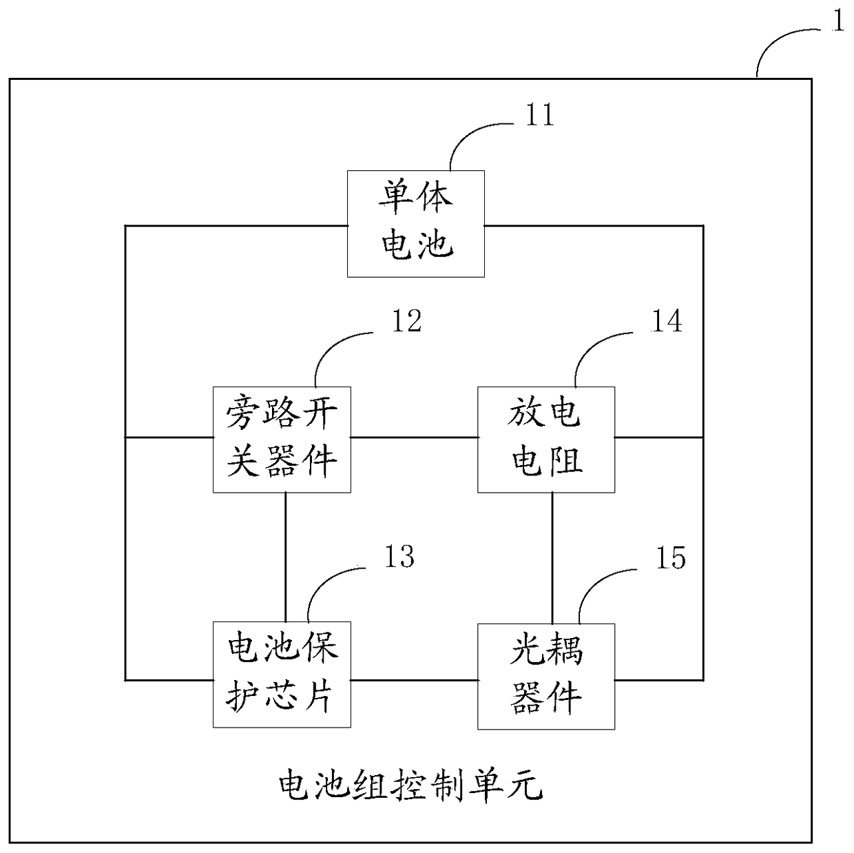
[0023] refer to figure 1 , figure 1 It is a structural block diagram of the battery pack control unit provided by the embodiment of the present invention, and is described in detail as follows:

[0024] A battery pack control unit, including a single battery, the battery pack control unit also includes:

[0025] Connect the bypass switch device of the single battery, connect the discharge resistor of the bypass switch device, the bypass switch device and the discharge resistor form a bypass connected in parallel to the single battery;

[0026] A battery protection chip connected in parallel to the bypass and controlling the conduction of the bypass switching device to discharge the bypass;

[0027] An optocoupler device that is connected in parallel with the discharge resistor and outputs a current down signal according to the voltage of the discharge resistor.

[0028] Wherein, the discharge resistor is used to share part of the current of the circuit where the single batt...

Embodiment 2

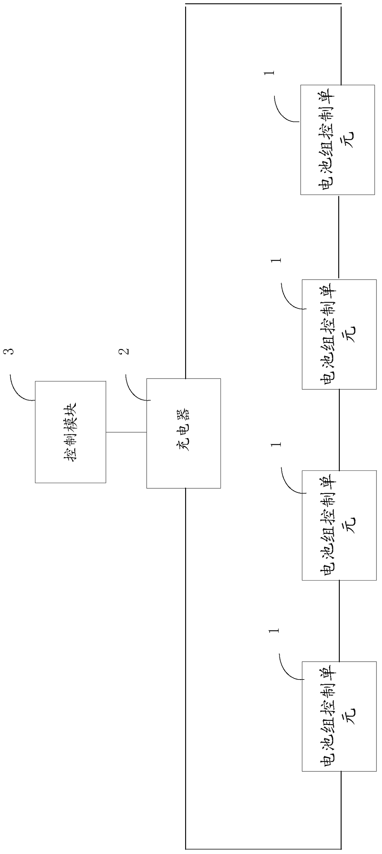
[0037] figure 2 It is a structural block diagram of the control system of the battery pack control unit provided by the embodiment of the present invention, and is described in detail as follows:

[0038] A control system for a battery pack control unit, comprising the above-mentioned battery pack control unit, a battery pack composed of a plurality of single cells in the battery pack control unit connected in series, the battery pack control unit control system further comprising:

[0039] a charger connected to said battery pack;

[0040] A control module connected to the charger and receiving the current lowering signal.

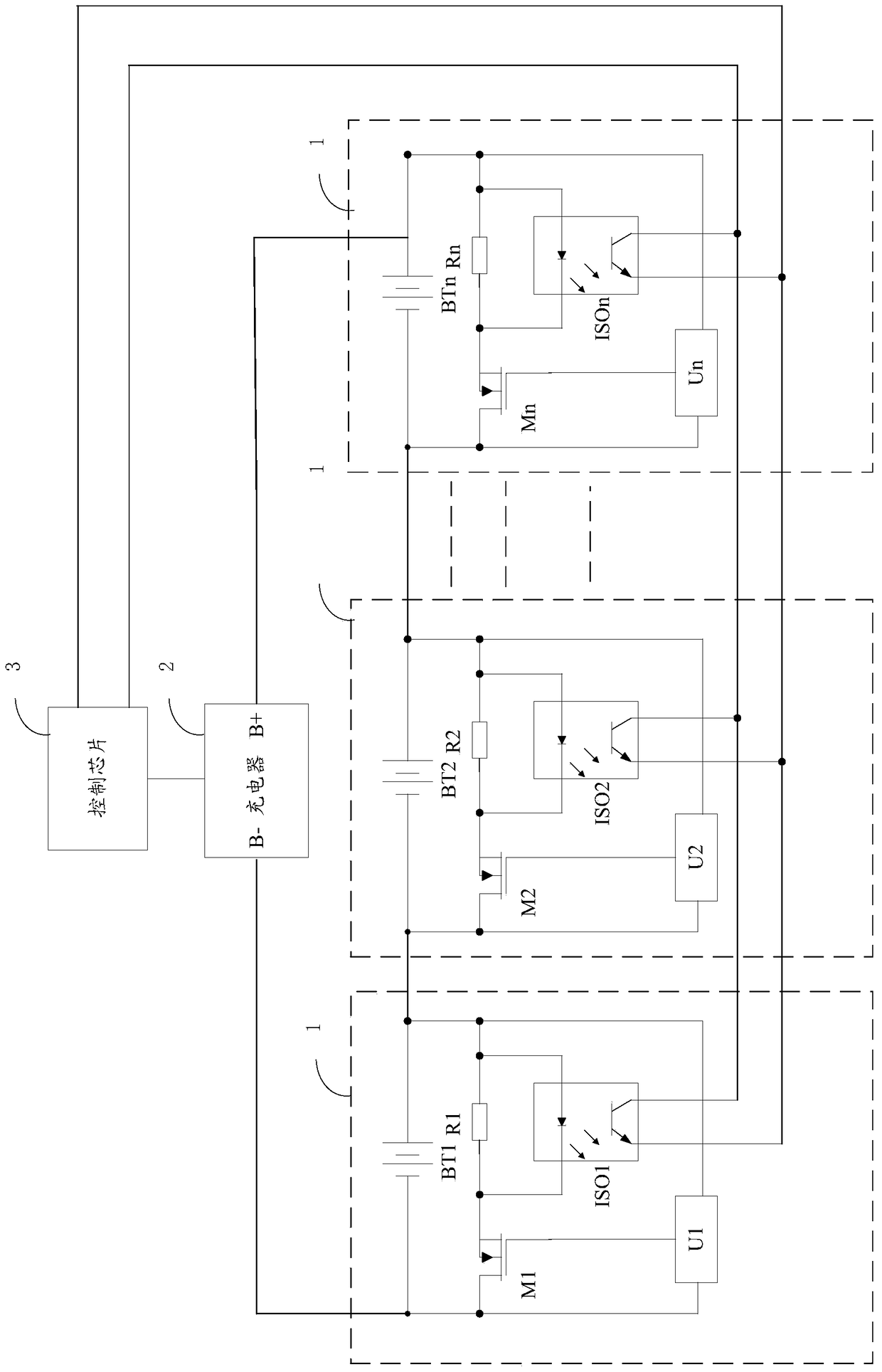
[0041] refer to image 3 , image 3 It is a preferred circuit diagram of the control system of the battery pack control unit provided by the embodiment of the present invention, and is described in detail as follows:

[0042] Among them, the single battery adopts BT1, BT2, BTn, the battery protection chip adopts U1, U2, Un, the bypass switch device a...

Embodiment 3

[0049] Figure 4 It is a flowchart for realizing the control method of the battery pack control unit control system provided by the embodiment of the present invention, and the control method includes:

[0050] S401. The battery protection chip in the battery pack control unit detects the voltage of a single battery, and when the voltage of the single battery is greater than a preset voltage, controls the bypass switching device to turn on, so that the bypass circuit discharge;

[0051] S402, the optocoupler device in the battery pack control unit outputs a current down signal according to the voltage of the discharge resistor;

[0052] S403. The control module receives a current reduction signal sent by the optocoupler device, and reduces the current passing through the single battery according to the current reduction signal.

[0053] Wherein, the battery protection chip detects the voltage of the single battery every preset time, and when the voltage of the single battery i...


PUM


Abstract

The invention is suitable for the field of battery control systems, and provides a battery-pack control unit, a control system and a control method. The battery-pack control unit comprises monomer cells, and further comprises a by-pass switch device connected with the monomer cells, a discharging resistor connected with the by-pass switch device, a battery protection chip and an optic coupler device, wherein a bypass connected to the monomer cells in parallel is formed by the bypass switch device and the discharging resistor; the battery protection chip is connected to the bypass in parallel, and controls the by-pass switch device to be on so that the bypass can discharge; the optic coupler device is connected to the discharging resistor in parallel and outputs electric-current lowering signals according to the voltage of the discharging resistor. According to the battery-pack control unit, the control system and the control method, the voltage differences between all the monomer cells in a battery pack are eliminated, so that under the condition that the battery pack is normally used, the reliability of keeping the consistent voltage of the monomer cells is improved, and it is also guaranteed that the electric quantity of all the monomer cells reaches the fully-charged capacity.

Description

technical field [0001] The invention belongs to the field of battery control systems, and in particular relates to a battery pack control unit, a control system and a control method. Background technique [0002] With the development of the new energy industry, multiple single cells can be connected in series to form a battery pack to provide power for related products. Battery overcharge and overdischarge phenomenon, thus affecting the normal use of the overall battery pack. Therefore, in the battery control system of the battery pack, various methods such as active management, passive management, energy transfer type, and energy consumption type will be used to keep the electric energy storage of each single battery in the battery pack tending to be consistent. [0003] However, in the existing battery control system, managing the voltage of each single battery is highly complicated and difficult to realize, which reduces the reliability of keeping the voltage of the sing...

Claims


Application Information

Patent Timeline
Patent Type & Authority Patents(China)
IPC IPC(8): H02J7/00
Inventor 李莉
Owner 深圳市瑞能创新科技有限公司
Why Eureka
Try Eureka