
Small Pneumatic Transfer Manipulator

A manipulator and pneumatic technology, applied in the field of small pneumatic conveying manipulators, can solve the problems of low efficiency and poor safety, achieve huge market prospects, meet the requirements of safe and efficient operation, and widely use the effect.

Active Publication Date: 2019-06-04
XIANGXIN AUTOMOTIVE COMPONENT TOOL & DIE
View PDF6 Cites 0 Cited by
  • Summary
  • Abstract
  • Description
  • Claims
  • Application Information

AI Technical Summary

Problems solved by technology

Manually complete the transfer of workpieces in the mold. Although ordinary stamping equipment can stamp the workpieces, there are problems such as low efficiency and poor safety, which cannot meet the safe and efficient operation requirements of modern industry.

Method used


Image

  • Small Pneumatic Transfer Manipulator
  • Small Pneumatic Transfer Manipulator

Examples


Embodiment

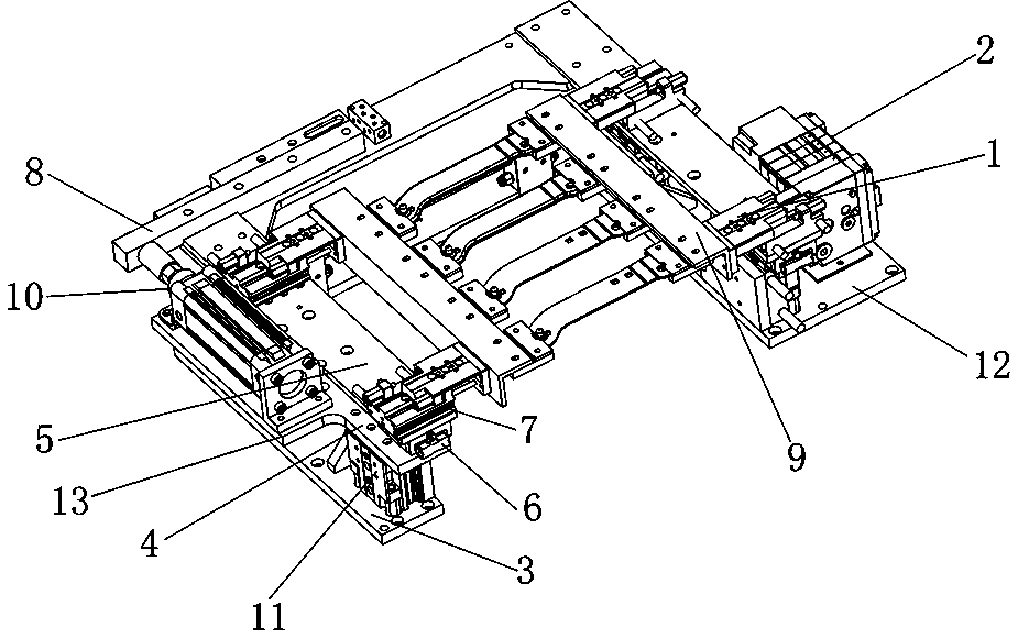
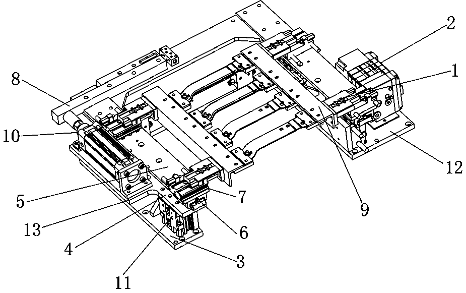
[0014] The model of horizontal cylinder 1 is SMC CQ2B 63-100, the model of air valve 2 is SMC EX260, the size of installation base 3 is 456mm*90 mm*15 mm; the size of installation base 12 with ear plate is 460 mm*200 mm*15 mm, the size of the ear plate is 210 mm*120 mm; the size of the support plate 4 is 600 mm*50 mm*15 mm; the size of the support plate 13 with the ear plate is 456 mm*155 mm*15 mm, and the size of the ear plate is The size is 320mm*70mm; the size of the longitudinal slide rail 6 is 180mm*42mm*15mm; the size of the horizontal slide rail 7 is 72mm*42mm*15mm; the size of the connecting beam 8 is 540mm*40mm* 30mm; the beam size of the horizontal manipulator 9 is 545 mm*80 mm*10 mm; the model of the vertical cylinder 10 is SMC MXH 20-60Z; the model of the ascending cylinder 11 is SMC MXH 20-60Z.


PUM


Abstract

The invention discloses a small pneumatic transmission manipulator applied to a stamping die. The small pneumatic transmission manipulator consists of air cylinders, an air valve, a mounting bottom plate, a supporting plate, a sliding rail connecting plate, sliding rails, a connecting beam and manipulator parts, wherein the number of lifting air cylinders is four; two longitudinal sliding rails are respectively arranged on the tail ends of the two flanks of the supporting plate; four transverse sliding rails are rectangularly arranged on the sliding rail connecting plate; four transverse air cylinders are arranged on the transverse sliding rails through slideways in the same direction; one transversely arranged manipulator part is arranged at the front ends of every two transverse air cylinders on the same side correspondingly; the longitudinal air cylinder is arranged on a lug plate of the supporting plate; the output top end of the longitudinal air cylinder is fixedly connected with the sliding rail connecting plate through the connecting beam; and the air valve is arranged on the mounting bottom plate and is in function connection with the air cylinders. With the design of the small pneumatic transmission manipulator, automatic production can be realized after common stamping equipment uses the small pneumatic transmission manipulator; the operation requirements on safety and high efficiency of stamping production in modern industry are met well; and the small pneumatic transmission manipulator has wide use requirements and huge market prospects.

Description

technical field [0001] A small pneumatic transfer robot used on stamping dies. Background technique [0002] Stamping processing is one of the various types of mechanical processing to meet the needs of various stamping parts processing. It has the characteristics of high efficiency, high quality, simplicity, and low carbon, and is widely used in the field of production and processing. [0003] When ordinary stamping equipment stamps stamping parts with the help of stamping dies, the transmission of workpieces in the dies needs to be done manually. Manually complete the transfer of the workpiece in the mold. Although ordinary stamping equipment can stamp the workpiece, it has problems such as low efficiency and poor safety, and cannot meet the safe and efficient operation requirements of modern industry. Contents of the invention [0004] The purpose of the present invention is to use the design of a small pneumatic transfer manipulator to enable common stamping equipment...

Claims


Application Information

Patent Timeline
Patent Type & Authority Patents(China)
IPC IPC(8): B21D43/10
CPCB21D43/105
Inventor 陈荣
Owner XIANGXIN AUTOMOTIVE COMPONENT TOOL & DIE
Learn More