Mounting trolley of welding backings for steel structure U-shaped ribbed plate

A technology for welding gaskets and steel structures, applied in welding equipment, welding accessories, arc welding equipment, etc., can solve the problems of workpiece welding penetration, failure to meet the design penetration requirements, and many reworks, so as to reduce friction, High practical value, simple operation effect

Active Publication Date: 2016-10-26
HUBEI TIANGAO BRIDGE ENG CO LTD
View PDF6 Cites 4 Cited by
  • Summary
  • Abstract
  • Description
  • Claims
  • Application Information

AI Technical Summary

Problems solved by technology

However, in order to meet this requirement, strict requirements must be imposed on the assembly process and welding process in the production process. In the welding process of existing welding methods, due to factors such as large assembly gap errors and no protective measures on the back of the weld seam, it is very easy to cause the workpiece to be weld...

Method used


Image

  • Mounting trolley of welding backings for steel structure U-shaped ribbed plate
  • Mounting trolley of welding backings for steel structure U-shaped ribbed plate
  • Mounting trolley of welding backings for steel structure U-shaped ribbed plate

Examples


Embodiment Construction

[0028] The present invention will be further described in detail below in conjunction with the accompanying drawings, so that those skilled in the art can implement it with reference to the description.

[0029] It should be understood that terms such as "having", "comprising" and "including" as used herein do not entail the presence or addition of one or more other elements or combinations thereof.

[0030] It should be noted that the experimental methods described in the following embodiments, unless otherwise specified, are conventional methods, and the reagents and materials, if not otherwise specified, can be obtained from commercial sources; in the description of the present invention, The terms "landscape", "portrait", "top", "bottom", "front", "rear", "left", "right", "vertical", "horizontal", "top", "bottom", The orientation or positional relationship indicated by "inner", "outer", etc. is based on the orientation or positional relationship shown in the drawings, whic...


PUM

PropertyMeasurementUnit
Widthaaaaaaaaaa

Abstract

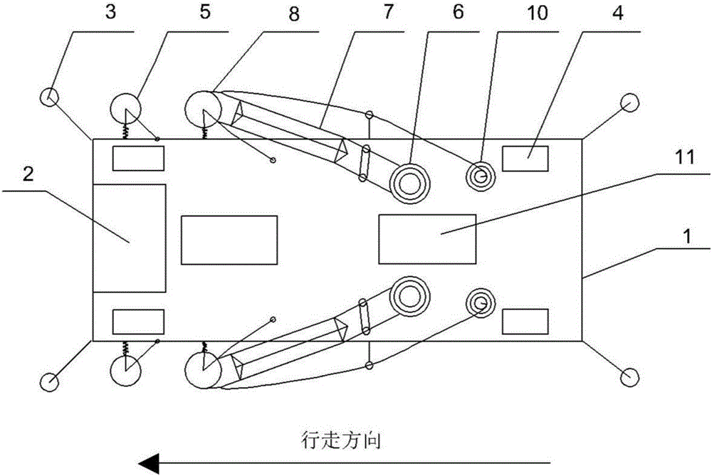
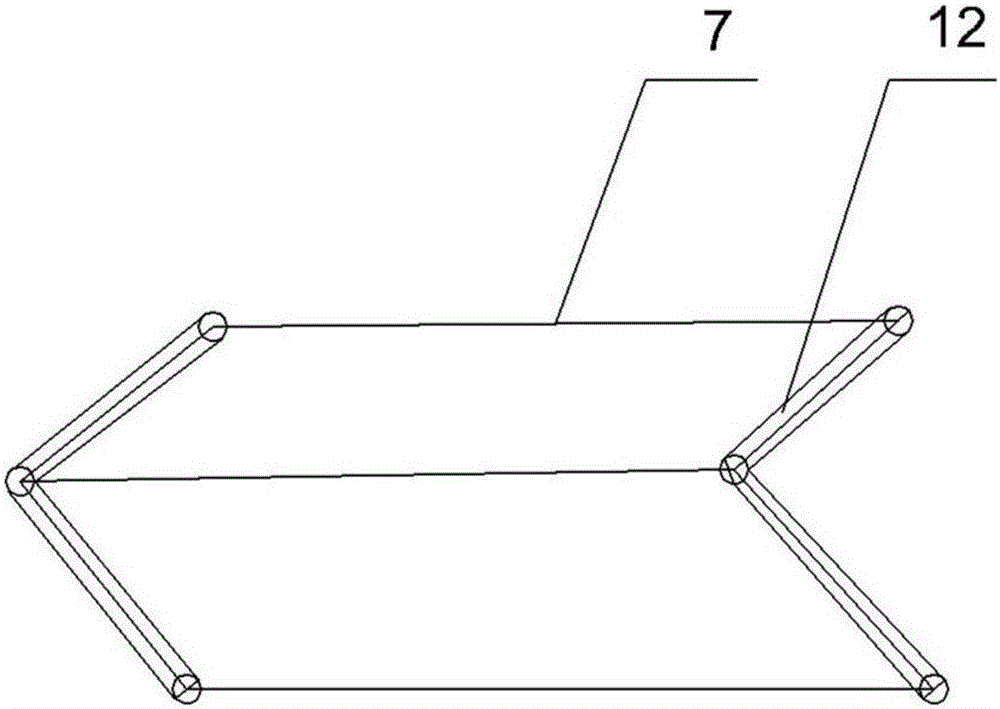
The invention discloses a mounting trolley of welding backings for a steel structure U-shaped ribbed plate. A pair of welding backings is symmetrically paved on an inner groove in a narrow and small space formed by a steel top plate and the U-shaped ribbed plate; the mounting trolley comprises a trolley body, a traveling mechanism, a reforming mechanism and an aluminum foil adhesive tape pre-deformation mechanism, wherein the traveling mechanism comprises at least two pair of guide wheels, at least two pairs of traveling wheels and a traveling motor; the reforming mechanism comprises at least one pair of first pressing wheels and at least one pair of first elastic members which are separately and symmetrically arranged; and the aluminum foil adhesive tape pre-deformation mechanism comprises a pair of pay-off wheels, a pay-off motor, a pair of V-shaped guide plates, a pair of second pressing wheels, a pair of second elastic members, a pair of hair brushes and a pair of third elastic members. According to the mounting trolley disclosed by the invention, the welding backings can be mounted in the narrow and small space on the back of a fillet weld of the steel structure U-shaped ribbed plate, the requirements on a welding process and an assembling process of a production field are loosened, the weld penetration of the fillet weld of the steel structure U-shaped ribbed plate is prevented, good positive and negative forming of the fillet weld is realized, the consumption of manpower and material resources is reduced, and the production efficiency and the quality are improved. The mounting trolley has relatively-high application value.

Description

technical field [0001] The invention relates to the technical field of bridge welding. More specifically, the present invention relates to a welded liner attaching trolley for steel structure U-shaped ribs. Background technique [0002] At present, the design requirements of U-shaped rib fillet welds on most steel structures at home and abroad are that the penetration depth is not less than 80% of the plate thickness, and there is no weld leakage, and the surface is smooth and even. However, in order to meet this requirement, strict requirements must be imposed on the assembly process and welding process in the production process. In the welding process of existing welding methods, due to factors such as large assembly gap errors and no protective measures on the back of the weld seam, it is very easy to cause the workpiece to be welded through. Or fail to meet the design penetration requirements, resulting in too much rework, the quality cannot be guaranteed, and because t...

Claims


Application Information

Patent Timeline
IPC IPC(8): B23K9/035B23K9/32
CPCB23K9/035B23K9/32
Inventor 胡文喜屠涛雄李华汪小根
Owner HUBEI TIANGAO BRIDGE ENG CO LTD
Why Eureka
Try Eureka