Equipment for precisely carving light guide plate by using laser

A light guide plate and laser technology, which is applied in laser welding equipment, welding equipment, metal processing equipment, etc., to achieve the effect of light equipment, reducing lost time and maximizing speed

Inactive Publication Date: 2016-10-26
合肥泰沃达智能装备有限公司
View PDF6 Cites 11 Cited by
  • Summary
  • Abstract
  • Description
  • Claims
  • Application Information

AI Technical Summary

Problems solved by technology

[0013] The object of the present invention is to provide a kind of equipment that uses laser to carry out precision engraving on the light guide plate, to solve the problems existing in the prior art laser engraving equipment

Method used


Image

  • Equipment for precisely carving light guide plate by using laser
  • Equipment for precisely carving light guide plate by using laser
  • Equipment for precisely carving light guide plate by using laser

Examples


Embodiment Construction

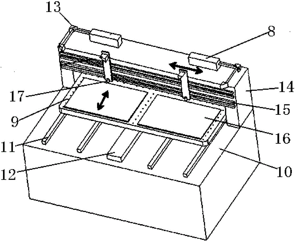
[0030] like Figure 4 — Figure 6 As shown, a device for precision engraving on a light guide plate with a laser, including a workbench 1, the top surface of the workbench 1 is provided with multiple guide rails 2 along the Y axis, that is, the horizontal front and rear directions, and the guide rails 2 of the workbench 1 are slidably equipped with The mobile platform 3, the top surface of the mobile platform 3 is used to carry the light guide plate 4, and the workbench 3 is provided with an optical rotation plate device 6 and a laser emitting device 5 from bottom to top in sequence;

[0031] Wherein the laser emitting device 5 includes a support plate 5.1 placed horizontally on the back and upper side of the workbench 3, the top surface of the support plate 5.1 is provided with a laser emitter 5.2, three groups of reflecting mirrors 5.3, 5.4, 5.5, and the first group of reflecting mirrors in the laser emitting device 5 The mirror 5.3 is located on the outgoing light path of ...


PUM


Abstract

The invention discloses equipment for precisely carving a light guide plate by using laser. The equipment comprises a worktable; multiple guide rails are arranged on the top surface of the worktable; a mobile platform is slidingly assembled on the guide rails of the worktable; the top surface of the mobile platform is used for bearing the light guide plate; and a cyclone light plate device and a laser emitting device are arranged on the back upper side of the worktable in sequence from bottom to top. The equipment can enable the light path to be minimal and the speed to be maximal, can reach minimal carving net point of 30 microns grade, can be simple and light, and greatly improves the production efficiency.

Description

technical field [0001] The invention relates to the field of laser engraving equipment, in particular to an equipment for precisely engraving a light guide plate with a laser. Background technique [0002] Displays as IT products are widely used in various forms such as LCD and LED. Among them, LED occupies the mainstream market because of its low energy consumption, high resolution, and large size. LEDs cannot be imaged after self-illumination, and imaging must be achieved through an imaging device, but the use of an imaging device requires a backlight to provide light. Backlights are divided into direct type and side-illuminated type according to the position distribution of the light source. As a representative of light and thin, side-illuminated type occupies the main middle and high-end market. [0003] In order to change the light source of the side-illuminated backlight from a line light source to a uniform surface light source, it is necessary to carry out precise ...

Claims


Application Information

Patent Timeline
Patent Type & Authority Applications(China)
IPC IPC(8): B23K26/362B23K26/08B23K26/064B23K26/70
CPCB23K26/08B23K26/064B23K26/361B23K26/70
Inventor 赵昌源张亚荣
Owner 合肥泰沃达智能装备有限公司
Why Eureka
Try Eureka