A thermal insulation cooling mechanism for electric spindle bearing seat

A heat insulation cooling and bearing seat technology, which is applied in the direction of metal processing machinery parts, maintenance and safety accessories, metal processing equipment, etc., can solve the problem of neglecting the heat isolation and evacuation of the stator and rotor of the motor, the poor cooling effect of the electric spindle bearing, and the impact on the bearing Use and other problems to achieve good heat insulation and cooling effects, good bearing overheating, and extended service life

Active Publication Date: 2018-01-05
NINGBO HAITIAN PRECISION MASCH CO LTD
View PDF8 Cites 0 Cited by
  • Summary
  • Abstract
  • Description
  • Claims
  • Application Information

AI Technical Summary

Problems solved by technology

When the temperature of the stator can be directly transmitted to the bearing seat through the air inside the motor, it will cause the bearing to overheat and affect the use of the bearing
[0003] At present, the cooling of the bearing seat of the electric spindle of the machine tool is mainly based on the traditional circulating cooling of the bearing seat, and the isolation and evacuation of the heat generated by the motor stator and rotor are ignored, that is, only dredging is considered in cooling, and the root cause is ignored. Isolation (other than heating of the bearings) and therefore less effective overall cooling of the motor spindle bearings

Method used


Image

  • A thermal insulation cooling mechanism for electric spindle bearing seat
  • A thermal insulation cooling mechanism for electric spindle bearing seat
  • A thermal insulation cooling mechanism for electric spindle bearing seat

Examples


Embodiment 1

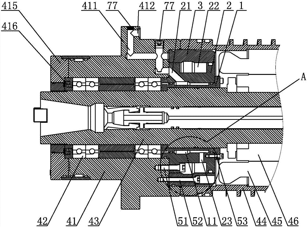
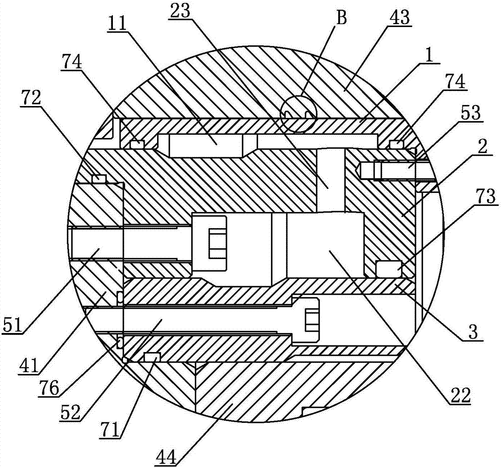
[0027]The heat insulation and cooling mechanism of the electric spindle bearing seat in Embodiment 1, as shown in the figure, the electric spindle bearing seat 41 is installed on the front end of the spindle 43, the bearing 42 is installed on the electric spindle bearing seat 41, and the electric spindle bearing seat 41 The rear side is equipped with a main shaft sleeve 44, and the inner side of the main shaft sleeve 44 is equipped with a motor stator 45 and a motor rotor 46. The heat ring 2 and the round sleeve 3, the outer heat insulating ring 2 is fixed on the rear end of the electric spindle bearing seat 41 by several first set screws 51, and the round sleeve 3 is fixed on the electric spindle bearing seat 41 by several second set screws 52 The inner heat insulating ring 1 is fixed on the outer heat insulating ring 2 through several third set screws 53, the round sleeve 3 is located on the inner side of the main shaft sleeve 44, the outer heat insulating ring 2 is located o...

Embodiment 2

[0029] The heat insulation and cooling mechanism of the electric spindle bearing seat in Embodiment 2, as shown in the figure, the electric spindle bearing seat 41 is installed on the front end of the spindle 43, the bearing 42 is installed on the electric spindle bearing seat 41, and the electric spindle bearing seat 41 The rear side is equipped with a main shaft sleeve 44, and the inner side of the main shaft sleeve 44 is equipped with a motor stator 45 and a motor rotor 46. The heat ring 2 and the round sleeve 3, the outer heat insulating ring 2 is fixed on the rear end of the electric spindle bearing seat 41 by several first set screws 51, and the round sleeve 3 is fixed on the electric spindle bearing seat 41 by several second set screws 52 The inner heat insulating ring 1 is fixed on the outer heat insulating ring 2 through several third set screws 53, the round sleeve 3 is located on the inner side of the main shaft sleeve 44, the outer heat insulating ring 2 is located ...


PUM


Abstract

The invention discloses a thermal insulation cooling mechanism of an electric main shaft bearing pedestal. The thermal insulation cooling mechanism comprises an inner thermal insulation ring, an outer thermal insulation ring and a circular sleeve, wherein an annular gap is formed between the inner thermal insulation ring and mandrel; an inner thermal insulation cavity is formed between the inner thermal insulation ring and the outer thermal insulation ring; an oblique hole is formed in the front end of the outer thermal insulation ring; a cooling loop and a first penetrating hole are arranged in the electric main shaft bearing pedestal; a first cooling liquid inlet and a first cooling liquid outlet are formed in the electric main shaft bearing pedestal; an outer thermal insulation cavity is formed between the outer thermal insulation ring and the circular sleeve; a second penetrating hole is formed in the outer thermal insulation ring; a crescent groove is formed in the circular sleeve; a first axial hole is formed in the front end of the circular sleeve; and a third penetrating hole is formed in the electric main shaft bearing pedestal. The thermal insulation cooling mechanism can effectively isolate heat generated by a motor stator and a motor rotor, timely transfers the heat to the external part of an electric main shaft to realize a better thermal insulation cooling effect, and is combined with the cooling loop to cool the electric main shaft bearing pedestal so as to prevent the bearing from being overheated and protect the bearing.

Description

technical field [0001] The invention relates to a cooling mechanism for a machine tool, in particular to a thermal insulation cooling mechanism applied to a bearing seat of an electric spindle of a high-speed electric spindle of a numerical control machine tool. Background technique [0002] With the development of built-in motor electric spindle technology, more and more CNC machine tools use electric spindle drive to replace the traditional motor-linked mechanical spindle drive. Compared with mechanical spindles, electric spindles have advantages such as high speed, zero transmission chain, and compact structure, but it is these advantages that pose severe challenges to the use of electric spindle bearings. The high speed of the electric spindle puts forward higher requirements for the use of bearings, especially the temperature rise caused by the friction of the bearing at high speed, which needs to be strictly controlled; in addition, the compact structure of the electri...

Claims


Application Information

Patent Timeline
Patent Type & Authority Patents(China)
IPC IPC(8): B23Q11/12
CPCB23Q11/127
Inventor 谢瑞木汪旭光唐科平饶磊邵明辉董威黄炜杰
Owner NINGBO HAITIAN PRECISION MASCH CO LTD
Why Eureka
Try Eureka