Water-cooling upper polishing disc structure of polishing machine

A polishing disk and polishing machine technology, applied in the polishing machine field, can solve the problems of uncontrollable changes in polishing disk temperature, no temperature control, etc., and achieve the effect of reliable cooling and temperature realization.

Inactive Publication Date: 2016-10-26
SUZHOU HRT ELECTRONICS EQUIP TECH
View PDF2 Cites 4 Cited by
  • Summary
  • Abstract
  • Description
  • Claims
  • Application Information

AI Technical Summary

Problems solved by technology

[0003] Previously, the polishing disc of the double-sided polishing machine used an integral structure without a special temperature control device. The heat generated during the polishing process was mainly taken away by the polishing liquid, which was passive cooling, and the temperature change of the polishing disc was uncontrollable.

Method used


Image

  • Water-cooling upper polishing disc structure of polishing machine
  • Water-cooling upper polishing disc structure of polishing machine
  • Water-cooling upper polishing disc structure of polishing machine

Examples


Embodiment Construction

[0018] The present invention will be described in detail below with reference to the accompanying drawings and in combination with embodiments.

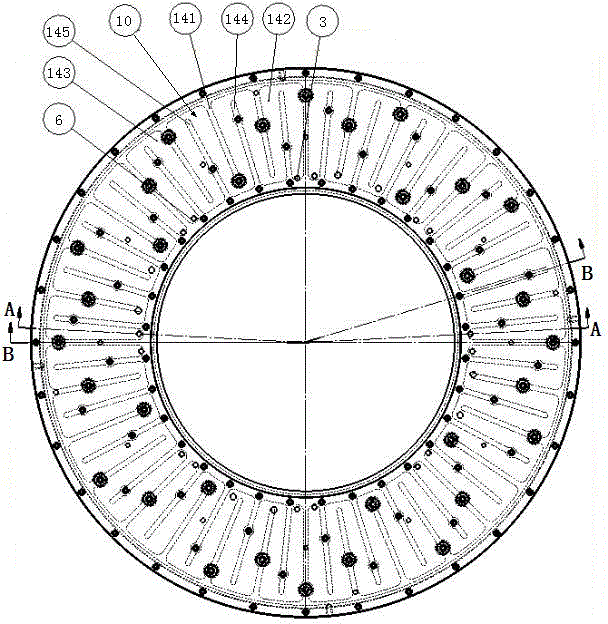
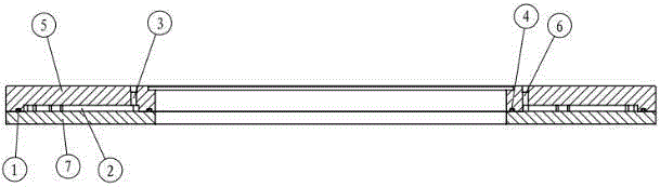
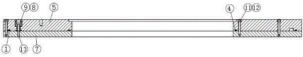
[0019] refer to Figure 1 to Figure 3 As shown, a water-cooled upper polishing disk structure of a polishing machine includes an upper disk working disk 7. In this embodiment, an upper disk water cooling disk 5 is provided on the upper end side of the upper disk working disk 7. The upper disk A cavity 2 is formed between the water cooling plate 5 and the upper plate working plate 7 , and a water inlet 3 and a water outlet 6 communicating with the cavity 2 are respectively provided on the upper plate water cooling plate 5 .

[0020] The cavity 2 is composed of a plurality of concave fan-shaped areas 14 provided on the upper plate water cooling plate 5, and each fan-shaped area 14 is divided into two interconnected inner concave water inlets by a protruding partition rib 141. A water inlet 3 is provided in the water inlet area 142 and...


PUM


Abstract

The invention relates to a water-cooled upper polishing disc structure of a polishing machine, which includes an upper disc working disc, an upper disc water cooling disc is arranged on one end side of the upper disc working disc, and a gap between the upper disc water cooling disc and the upper disc working disc A cavity is formed, and a water inlet and a water outlet communicated with the cavity are respectively arranged on the upper plate water cooling plate. The water cooling plate structure of the present invention is composed of several mutually independent cavities, each cavity has its own independent water inlet and outlet, and its water path is a reciprocating labyrinth, which effectively avoids shortcuts for cooling water and ensures Only after the cavity can flow out from the water outlet, it is helpful for the cooling water to fully cool the upper working plate and take away the heat generated by processing in time, thus playing a role in forced cooling of the throwing plate, which is more reliable than traditional passive cooling .

Description

technical field [0001] The invention relates to the technical field of polishing machines, in particular to a water-cooled upper polishing disc structure of the polishing machine. Background technique [0002] The upper polishing disc of the polishing machine used for thin and brittle materials such as silicon wafers will generate a lot of heat during the polishing process, and the temperature change will inevitably cause the deformation of the polishing disc, which will affect the processing quality. Therefore, the temperature of the polishing disc must be strictly controlled. . In recent years, the size of silicon wafers for IC processing tends to be larger in diameter, and the quality requirements for the morphology of silicon wafers are becoming more and more stringent. For polishing equipment used for double-sided polishing of silicon wafers, the deformation of the polishing disc must be strictly controlled. The water cooling structure of the upper polishing disc is ma...

Claims


Application Information

Patent Timeline
Patent Type & Authority Applications(China)
IPC IPC(8): B24B55/02B24B41/047
CPCB24B55/02B24B41/047
Inventor 乔卫民李方俊翟新马艳
Owner SUZHOU HRT ELECTRONICS EQUIP TECH
Why Eureka
Try Eureka