
Water-cooling lower polishing disc structure of polishing machine

A polishing disc and polishing machine technology, which is applied in the direction of grinding/polishing equipment, grinding/polishing safety devices, grinding heads, etc., and can solve the problems of uncontrollable changes in the temperature of the polishing disc and poor cooling effect

Inactive Publication Date: 2016-11-02
SUZHOU HRT ELECTRONICS EQUIP TECH
View PDF7 Cites 0 Cited by
  • Summary
  • Abstract
  • Description
  • Claims
  • Application Information

AI Technical Summary

Problems solved by technology

[0003] The bottom throwing plate of the single-side polishing machine produced before is also equipped with a water cooling plate, the cooling effect is not good, and the change of the throwing plate temperature is uncontrollable

Method used


Image

  • Water-cooling lower polishing disc structure of polishing machine
  • Water-cooling lower polishing disc structure of polishing machine

Examples


Embodiment Construction

[0017] The present invention will be described in detail below with reference to the accompanying drawings and in combination with embodiments.

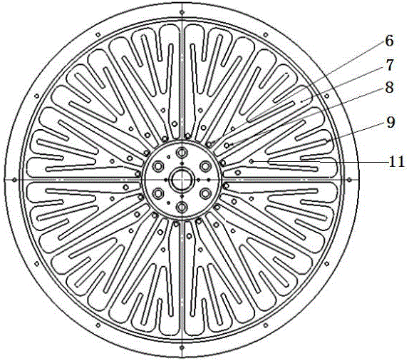
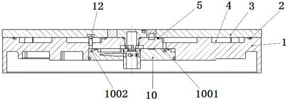
[0018] refer to figure 1 and figure 2 As shown, a water-cooled lower polishing disc structure of a polishing machine includes a lower disc working disc 3, a water cooling disc 1 is provided below the lower disc working disc 3, and the connection between the water cooling disc 1 and the lower disc working disc 3 There is a cooling chamber 4 between them, the water cooling plate 1 is provided with a water inlet 6 and a water outlet 8, and the water cooling plate 1 is provided with a fan-shaped cooling chamber 7, and the fan-shaped cooling chamber 7 is provided with a shunt rib 9.

[0019] Further, the outer ring between the water cooling plate 1 and the lower working plate 3 is provided with an outer ring sealing ring 2 , and the inner ring is provided with an inner ring sealing ring 5 .

[0020] Preferably, the inner middle positio...


PUM


Abstract

The invention discloses a water-cooling lower polishing disc structure of a polishing machine. The structure comprises a lower disc working disc; a water cooling disc is arranged below the lower disc working disc; a cooling cavity is formed between the water cooling disc and the lower disc working disc; a water inlet and a water outlet are formed in the water cooling disc; a fan-shaped cooling cavity is formed in the water cooling disc; and shunt ribs are arranged in the fan-shaped cooling cavity. The structure adopts the special water cooling disc structure to prevent cooling water from cutting corners, guarantees the cooling water to flow out from the water outlet only after being fully filled in the cavity, guarantees the cooling water to fully cool the polishing disc, timely takes away heat generated by machining to achieve a forced cooling effect on the polishing disc, is more reliable compared with traditional passive cooling, and is combined with a precise temperature measuring system and a cooling water flow adjusting system to realize precise temperature control of the polishing disc.

Description

technical field [0001] The invention relates to the structure of a polishing machine, in particular to a water-cooled polishing disk structure of the polishing machine. Background technique [0002] The lower polishing disc used in the polishing machine will generate a lot of heat during the polishing process, and the temperature change will inevitably cause the deformation of the polishing disc, which will affect the processing quality, so the temperature of the polishing disc must be strictly controlled. In recent years, the size of silicon wafers for IC chips tends to be larger in diameter, and the quality requirements for silicon wafers are becoming more and more stringent. For polishing equipment used for single-sided polishing of silicon wafers and other high-precision thin and brittle materials, the throwing of the disc must be strictly controlled. deformation. [0003] The lower throwing plate of the single-side polishing machine produced before is also equipped wit...

Claims


Application Information

Patent Timeline
Patent Type & Authority Applications(China)
IPC IPC(8): B24B55/02B24B41/047
CPCB24B55/02B24B41/047
Inventor 乔卫民翟新李方俊马艳
Owner SUZHOU HRT ELECTRONICS EQUIP TECH
Learn More