Mechanical arm for installing internal spring of machine and working method thereof

A technology of mechanical arms and working methods, which is applied in the directions of manipulators, metal processing, manufacturing tools, etc., can solve the problems of poor installation of springs, and achieve the effects of avoiding damage to springs, convenient grasping of springs, and solving problems of poor installation

Active Publication Date: 2018-06-29
南京宁信安躿医疗科技有限公司
View PDF7 Cites 0 Cited by
  • Summary
  • Abstract
  • Description
  • Claims
  • Application Information

AI Technical Summary

Problems solved by technology

[0004] The purpose of the invention: the present invention discloses a mechanical arm for installing the internal spring of the machine, which can replace the manual spring installation, greatly improve the production efficiency, solve the problem that the internal spring of the machine is not easy to install, and can deal with complex actual situations; after the installation is completed , directly detect the spring force, once the installation is detected to be unqualified, it will be reinstalled automatically
This design replaces the manual installation of springs, which greatly improves production efficiency and solves the problem of difficult installation of springs inside the machine; the combination of electromagnetic suction cups and spring jaws makes it more convenient to grab springs and the installation process is more reliable; the design of auxiliary jaws It can cope with complex actual situations and help installation; after the installation is completed, the pressure sensor will detect the spring force, and once the installation is detected to be unqualified, the control device will issue an instruction to automatically reinstall

Method used


Image

  • Mechanical arm for installing internal spring of machine and working method thereof
  • Mechanical arm for installing internal spring of machine and working method thereof
  • Mechanical arm for installing internal spring of machine and working method thereof

Examples


Embodiment

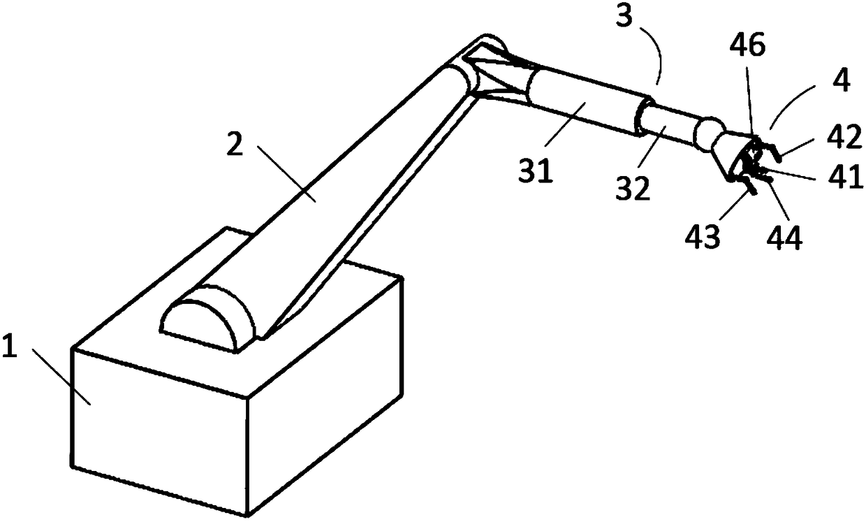
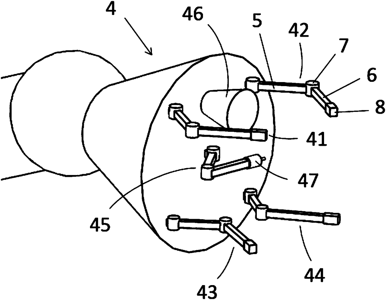
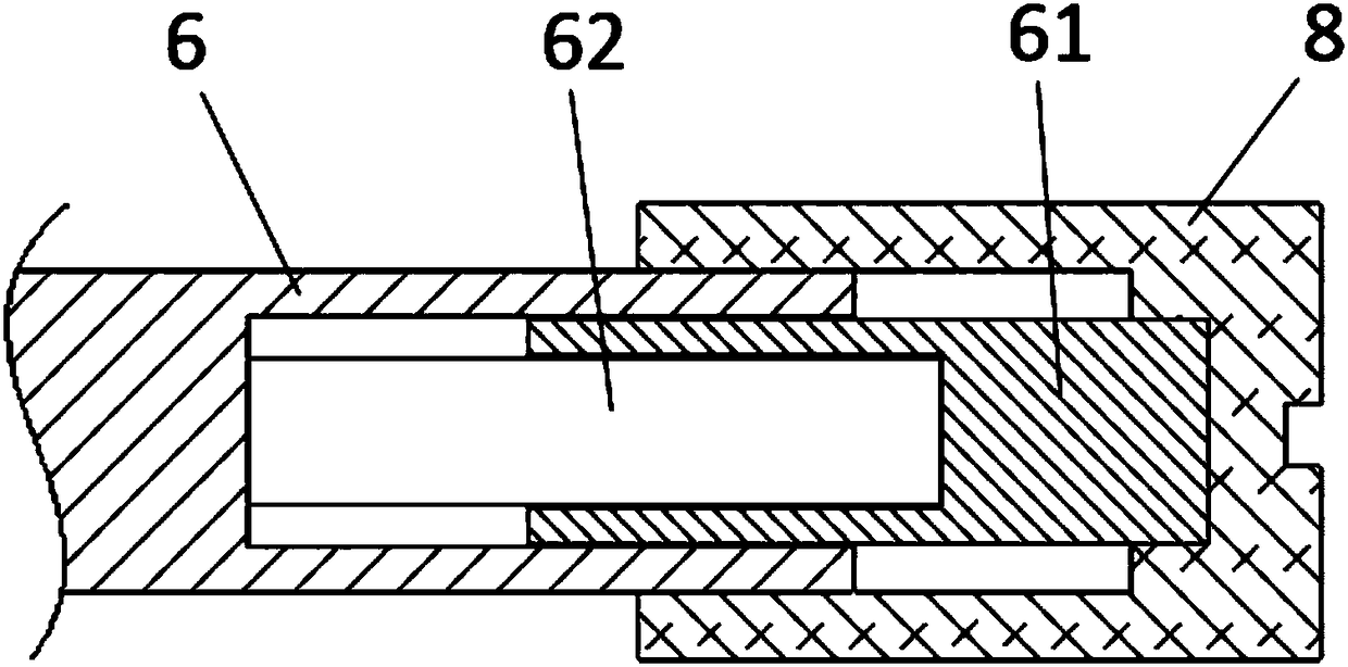
[0021] A mechanical arm for installing the internal spring of the machine of the present invention, such as Figure 1 to Figure 3 As shown, it includes a base 1, a first mechanical arm 2, a second mechanical arm 3, a manipulator 4, a driving device and a control device; the manipulator 4 includes a spring left jaw 41 and a spring right jaw 42 oppositely arranged, A pair of oppositely arranged auxiliary left jaws 43, auxiliary right jaws 44, and detection jaws 45, wherein the spring left jaws 41, spring right jaws 42, auxiliary left jaws 43 and auxiliary right jaws 44 all include upper jaws The jaw 5, the lower jaw 6 and the jaw joint 7 connecting the two, an electromagnetic sucker 46 is provided between the spring left jaw 41 and the spring right jaw 42, and a pressure sensor 47 is provided at the end of the detection jaw 45; The first mechanical arm 2, the second mechanical arm 3 and the manipulator 4 are all connected to the driving device, and the electromagnetic chuck 46, ...


PUM


Abstract

A mechanical arm for mounting of spring in a machine comprises a base, a first mechanical arm body, a second mechanical arm body, a mechanical hand, a drive device and a control device. The mechanical hand comprises a left spring clamping jaw, a right spring clamping jaw, a pair of left auxiliary clamping jaw and right auxiliary clamping jaw and a detection claw, wherein the left spring clamping jaw and the right spring clamping jaw are arranged oppositely, and the left auxiliary clamping jaw and the right auxiliary clamping jaw are arranged oppositely. The left spring clamping jaw, the right spring clamping jaw, the left auxiliary clamping jaw and the right auxiliary clamping jaw each comprise an upper clamping jaw body, a lower clamping jaw body and a clamping jaw joint connected with the upper clamping jaw body and the lower clamping jaw body. An electromagnetic chuck is arranged between the left spring clamping jaw and the right spring clamping jaw. A pressure sensor is arranged at the end of the detection claw. The first mechanical arm body, the second mechanical arm body and the mechanical hand are all connected with the drive device. The electromagnetic chuck, the pressure sensor and the drive device are all connected with the control device. By means of the design, manpower is replaced for mounting the spring, production efficiency is greatly improved, and the problem that the spring in the machine is hard to mount is solved.

Description

technical field [0001] The invention relates to the technical field of mechanical arms, in particular to a mechanical arm for installing internal springs of machines. Background technique [0002] Due to the complex installation environment of the spring, the installation method is often changed. At present, the installation of the spring is mostly manual installation. Viewfinders also greatly affect production efficiency, and the installation quality is not easy to guarantee; in addition, when the spring force required to install the spring is large, manual operation is more difficult, which requires an automated spring installation system to replace manual installation. operation, and can cope with the complex installation environment of the spring. [0003] In addition, the spring installation may be unqualified, or the spring force may not meet the standard after installation, which requires effective testing after the installation is completed, but ordinary position te...

Claims


Application Information

Patent Timeline
Patent Type & Authority Patents(China)
IPC IPC(8): B25J15/06B25J15/08B25J13/08B23P19/04
CPCB23P19/048B25J13/085B25J15/0608B25J15/08
Inventor 苏皓
Owner 南京宁信安躿医疗科技有限公司
Why Eureka
Try Eureka