Punching machine with fixing function

A fixed function, punching machine technology, applied in the field of punching machines, can solve problems such as deviation of punching position, achieve the effect of accurate hole position, avoid damage and waste

Inactive Publication Date: 2016-10-26
无锡博成洋超声设备有限公司
View PDF8 Cites 1 Cited by
  • Summary
  • Abstract
  • Description
  • Claims
  • Application Information

AI Technical Summary

Problems solved by technology

[0005] Aiming at the deficiencies of the prior art, the present invention provides a punching machine with a fixed function, which solves the situation that the position of the punching hole is deviated due to the fact that the object is not fixed when punching the hole

Method used


Image

  • Punching machine with fixing function
  • Punching machine with fixing function
  • Punching machine with fixing function

Examples


Embodiment Construction

[0024] The following will clearly and completely describe the technical solutions in the embodiments of the present invention with reference to the accompanying drawings in the embodiments of the present invention. Obviously, the described embodiments are only some, not all, embodiments of the present invention. Based on the embodiments of the present invention, all other embodiments obtained by persons of ordinary skill in the art without making creative efforts belong to the protection scope of the present invention.

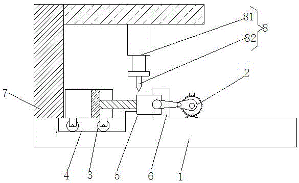
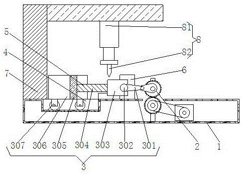
[0025] The invention provides a punching machine with fixed functions, such as figure 1 As shown, including the base 1, the inner wall of the base 1 is fixedly connected with the driving device 2, and the top of the base 1 is fixedly connected with the bearing seat 5 and the fixed extrusion block 6, and one side of the bearing seat 5 is connected with the fixed extrusion block 6. One side is in contact, the top of the base 1 is fixedly connected with a support...


PUM


Abstract

The invention discloses a punching machine with a fixing function. The punching machine comprises a base. A drive device is fixedly connected to the inner wall of the base and comprises a motor. The motor is fixedly connected to the inner wall of the base. A first belt wheel is fixedly connected to a rotating shaft of the motor and movably connected with the surface of a second belt wheel through a belt. The second belt wheel is fixedly connected to the surface of a first gear. According to the punching machine with the fixing function, through matched usage of the motor, the first belt wheel, the belt, the second belt wheel, the first gear and a second gear, an object can be well fixed during punching, and the situation that in the object punching process, due to the fact that fixation is not adopted, deviation of the punching position happens is avoided; and through the arrangement of a connecting plate, a connecting block, a push and pull rod and a movable extrusion block, the object cannot swing in the punching process, and therefore the position of a hole of the object is more accurate in the punching process, and the object is prevented from being damaged and wasted.

Description

technical field [0001] The invention relates to the technical field of machinery, in particular to a punching machine with a fixed function. Background technique [0002] The punching machine is composed of four parts that cooperate with each other to complete the punching process. First, move the material to the scanning area of ​​the camera of the automatic punching machine. After the camera scans the image, it will process it and send a signal to the control part. After the control part receives the signal, it will further process and control the action of the transmission part, so that the punch is X on the plane. Axis, Y axis move, the pneumatic part starts to work after the movement is completed, and the solenoid valve controls the cylinder to perform the punching action. The automatic punching machine punches the printing positioning holes, and the whole action is done in one go, fast, accurate and efficient. [0003] At present, the existing punching machines on th...

Claims


Application Information

Patent Timeline
IPC IPC(8): B26F1/24B26D7/01
CPCB26F1/24B26D7/01
Inventor 叶乔
Owner 无锡博成洋超声设备有限公司
Why Eureka
Try Eureka