Radio frequency/microwave blind-mate connector array positioning method

A positioning method and connector technology, which is applied in the direction of connection, assembly/disassembly of circuit/collector components, contact pieces, etc., to achieve the effects of facilitating equipment assembly, improving assembly quality, and shortening assembly adjustment time

Pending Publication Date: 2021-12-31
10TH RES INST OF CETC
View PDF5 Cites 0 Cited by
  • Summary
  • Abstract
  • Description
  • Claims
  • Application Information

AI Technical Summary

Problems solved by technology

[0004] The purpose of the present invention is to address the shortcomings of the above-mentioned prior art, to provide a method that is easy to operate, reliable in positioning, low in cost, and capable of overall positioning of large-scale, miniaturized, and high-density bidirectional plug arrays, so as to solve the problem of large-scale connectors. High Density Array Positioning Assembly Issues

Method used


Image

  • Radio frequency/microwave blind-mate connector array positioning method
  • Radio frequency/microwave blind-mate connector array positioning method
  • Radio frequency/microwave blind-mate connector array positioning method

Examples


Embodiment Construction

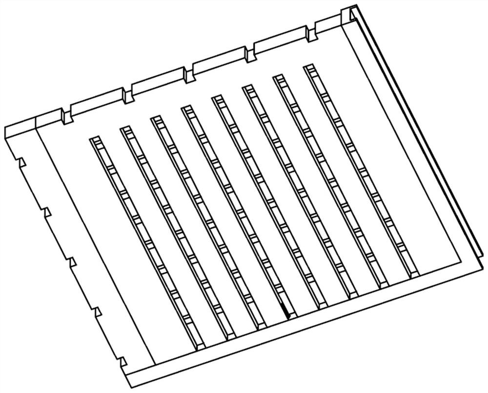
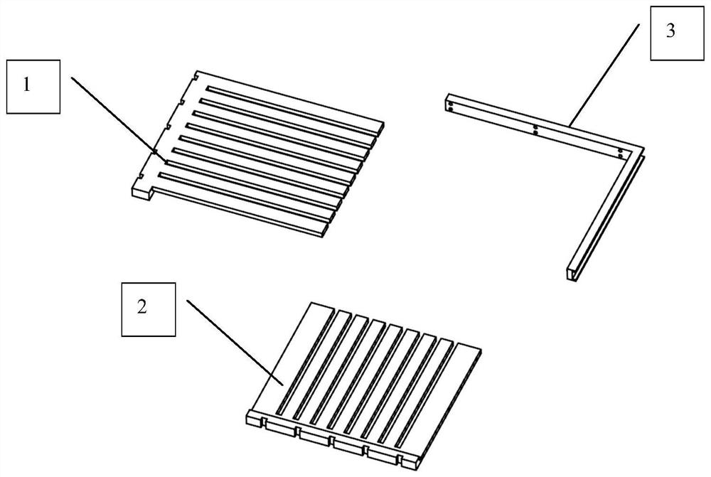
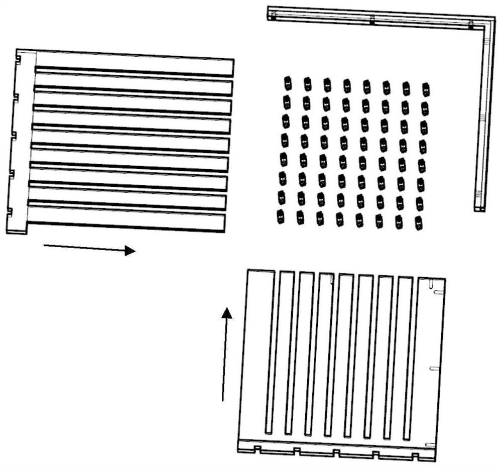
[0020] refer to Figure 1-Figure 5 . According to the present invention, first prepare a finger-shaped fixture that can limit the two-way plugs of all radio frequency blind mating connector arrays in the vertical and horizontal intersecting finger grids of two sets of positioning finger boards; then when assembling, first connect the radio frequency blind mating All array bidirectional plugs of the device are inserted one by one into the socket blind-matching jack of one of the microwave component modules to form a matrix of radio frequency bidirectional plug arrays; Two directions are cross-inserted into the array area of ​​the RF bidirectional plug, and two sets of vertically and horizontally stacked positioning fingers form an intersecting grid between the matrix rows and columns of the RF bidirectional plug; 1 and the horizontal positioning finger board 2 are intersected to form a rectangular right-angled side; each hole in the grid of the two sets of positioning finger b...


PUM


Abstract

A radio frequency / microwave blind-mate connector array positioning method disclosed by the invention is convenient to operate, reliable in positioning and low in cost. The method is realized through the following steps: preparing a finger-shaped clamp capable of limiting all radio frequency blind-mate connector array bidirectional plugs in a vertically and horizontally crossed finger insertion grid of two groups of positioning finger insertion plates; then, during assembly, inserting the longitudinal positioning finger insertion plate and the transverse positioning finger insertion plate into an array area of a radio frequency bidirectional plug in a crossed mode in the longitudinal direction and the transverse direction respectively, and forming crossed grids between matrix row and column interval channels of the radio frequency bidirectional plug through the longitudinal positioning finger insertion plate and the transverse positioning finger insertion plate which are stacked up and down; then, fixing rectangular right-angle sides formed by intersection of the longitudinal positioning finger insertion plates and the transverse positioning finger insertion plates through L-shaped angle square positioning pieces; and positioning the relative plane positions of all the radio frequency bidirectional plugs by virtue of the cooperation of the pore size of the crossed grid and the boundary dimension of the connector, so as to complete the overall positioning of the high-density bidirectional plugs of the radio frequency blind-mating connector array between the microwave components.

Description

technical field [0001] The invention relates to a cross-finger positioning method mainly used for positioning radio frequency connector groups installed in arrays. Background technique [0002] At present, microwave component modules are developing in the direction of miniaturization and integration, and the degree of equipment integration is getting higher and higher. The number of electrical connections required on each module has increased significantly. The application of blind mating RF coaxial connector arrays in microwave systems is also increasing. more and more widely. Components and modules are directly connected by miniaturized and large-scale blind mating RF coaxial connector arrays, which has become a common connection method for microwave component modules. For example, preamplifiers, intermediate frequency amplifiers, dual A-balanced mixers, directional couplers, switch matrix circuits, and even entire receivers can be connected using blind-mate connectors. ...

Claims


Application Information

Patent Timeline
Patent Type & Authority Applications(China)
IPC IPC(8): H01R43/20
CPCH01R43/205
Inventor 李燚卢健钊
Owner 10TH RES INST OF CETC
Why Eureka
Try Eureka