
Hot runner mold structure

A hot runner and mold technology, applied in the field of hot runner mold structure, can solve problems such as low production efficiency and material retention, and achieve the effects of solving material retention, improving production efficiency, and ensuring product quality

Inactive Publication Date: 2016-10-26
SHIYAN DEYUAN TECH DEV
View PDF0 Cites 1 Cited by
  • Summary
  • Abstract
  • Description
  • Claims
  • Application Information

AI Technical Summary

Problems solved by technology

[0005] The inside of the runner is at right angles, and the product will stay in the mold when it flows in the mold, and the production efficiency is low

Method used


Image

  • Hot runner mold structure

Examples


Embodiment Construction

[0018] In order to make the object, technical solution and advantages of the present invention clearer, the implementation manner of the present invention will be further described in detail below in conjunction with the accompanying drawings.

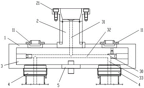
[0019] The embodiment of the present invention provides a hot runner mold structure, see figure 1 , the hot runner mold structure is applied to the hot runner mold, and the hot runner mold structure includes a fixed template 1, a main gate 2 arranged on the fixed template 1, a manifold 3 connected to the main gate 1, and a manifold 3 connected to the sub-gate 4, and the central positioning pin 5 arranged at the end of the manifold 3.

[0020] Specifically, spacers 11 are arranged symmetrically at both ends of the fixed template 1 .

[0021] Specifically, a positioning ring 21 is provided on the main gate 2 .

[0022] Specifically, a runner is provided in the manifold 3, and the runner includes a main runner 31, a secondary runner 32 ...


PUM


Abstract

The invention discloses a hot runner mold structure, which belongs to the field of molds. The hot runner mold structure includes a fixed plate, a main gate arranged on the fixed plate, a manifold connected to the main gate, a sub-gate connected to the manifold, and a gate arranged on the manifold The central positioning pin at the end; the flow channel is provided in the splitter plate, and the flow channel includes a main flow channel, a secondary flow channel and a branch flow channel; the main flow channel is arranged in the main gate, and the secondary flow channel and The main channel is connected, and the sub-runner is connected with the secondary channel; the corners of the main channel, the secondary channel and the sub-channel are curved; the main channel, the secondary channel The cross-sections of the flow channel and the branch channel are located in the same plane. The invention effectively solves the problem of material retention when the product flows in the mould, ensures the product quality and effectively improves the production efficiency through the bend angle arranged in the flow channel.

Description

technical field [0001] The invention relates to the field of molds, in particular to a hot runner mold structure. Background technique [0002] Hot runner mold is a kind of plastic injection molding mold commonly used at present. Compared with mold with cold runner structure, it has many advantages such as saving raw materials, improving production efficiency, improving product quality, and simplifying product follow-up processes. [0003] At present, the existing runner is composed of three parts: the main runner, the secondary runner and the sub-runner. The above-mentioned runners are set in a special mold. The plane where the channels are located is perpendicular to each other. When the material is injected into the mold from the nozzle of the molding machine, it must first pass through the main channel, and then be injected into each secondary channel through the injection pressure of the molding machine, and finally enter the cavity through the sub-runner. [0004] I...

Claims


Application Information

Patent Timeline
Patent Type & Authority Applications(China)
IPC IPC(8): B29C45/27
CPCB29C45/27
Inventor 郑辉
Owner SHIYAN DEYUAN TECH DEV
Learn More