Laser overhead contact system wire inspection device and method

A catenary and wire technology, applied in the direction of optical devices, measuring devices, overhead lines, etc., can solve problems such as unsuitable detection, large measurement errors, and large weather effects

Active Publication Date: 2016-10-26
CHINA CREC RAILWAY ELECTRIFICATION BUREAU GRP
View PDF6 Cites 15 Cited by
  • Summary
  • Abstract
  • Description
  • Claims
  • Application Information

AI Technical Summary

Problems solved by technology

This method has large measurement errors, few parameters, and is greatly affected by the weather. It is not suitable for detection when there is wind, rain, or fog.
Commonly used catenary measuring instrument, manual operation, artificial aiming point, can not measure continuously

Method used


Image

  • Laser overhead contact system wire inspection device and method
  • Laser overhead contact system wire inspection device and method
  • Laser overhead contact system wire inspection device and method

Examples


Embodiment Construction

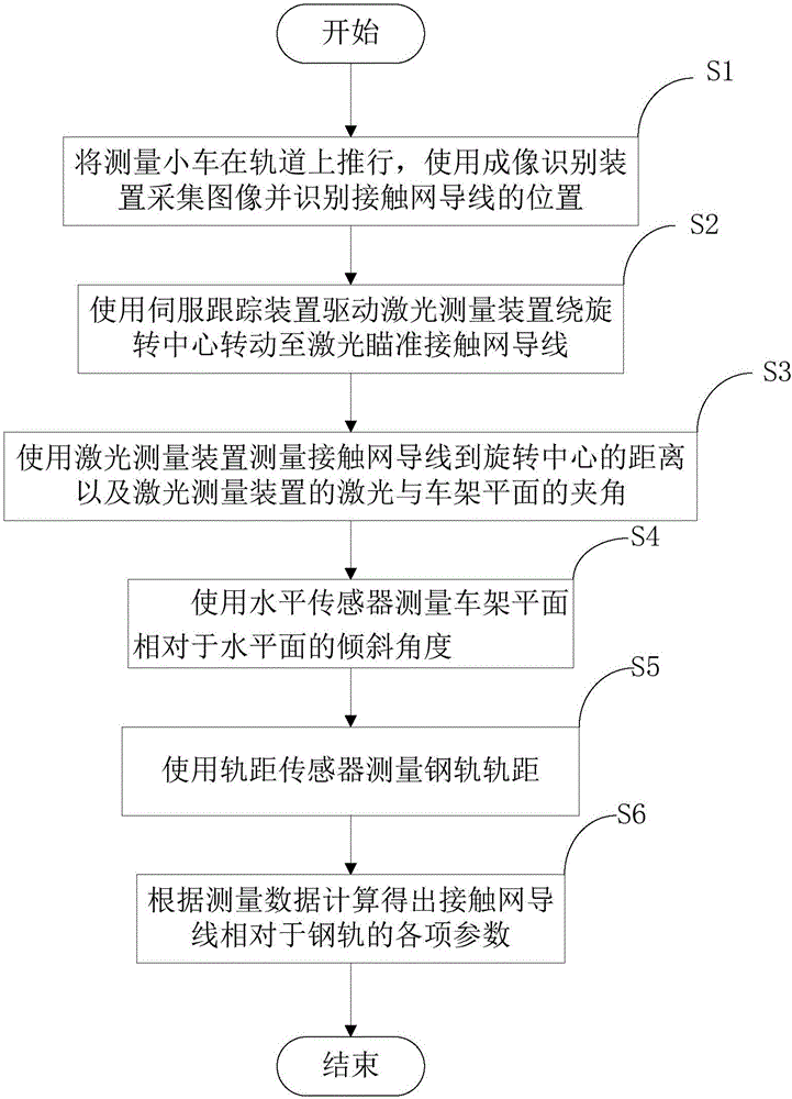
[0031] The present invention will be described in further detail below in conjunction with the accompanying drawings and embodiments.

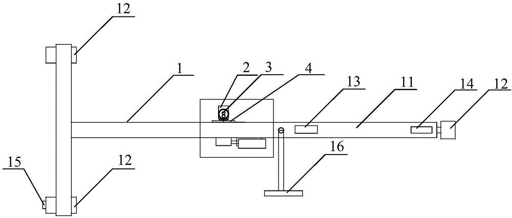
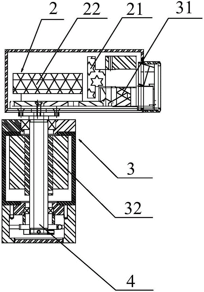
[0032] see figure 1 As shown, the embodiment of the present invention provides a laser catenary wire inspection device, including: a measuring trolley 1, the measuring trolley 1 includes a T-shaped vehicle frame 11 and three wheels 12, and the wheels 12 are respectively arranged on the vehicle frame 11 and three wheels. two endpoints; vehicle frame 11 is provided with a level sensor 13 and a gauge sensor 14; imaging recognition device 2, imaging recognition device 2 is located on the vehicle frame 11, imaging recognition device 2 is used for collecting images and identifying the position of catenary wire Position; Laser measuring device 3, laser measuring device 3 is located on vehicle frame 11, and laser measuring device 3 comprises a rotation center 33, and laser measuring device 3 is used for measuring the distance of catenary wire to rotat...


PUM


Abstract

The invention discloses a laser overhead contact system wire inspection device and method, and relates to the technical field of tramcar detection. The device comprises a measuring trolley, an imaging recognition device, a laser measuring device and a servo tracking device; the measuring trolley comprises a T-shaped frame and three wheels arranged at three endpoints of the frame respectively, and the frame is provided with a horizontal sensor and a track gauge sensor; the imaging recognition device is arranged on the frame and used for collecting an image and recognizing the position of an overhead contact system wire; the laser measuring device is arranged on the frame, comprises a rotating center and is used for measuring the distance between the overhead contact system wire and the rotating center and an included angle between lasers of the laser measuring device and a frame plane; the servo tracking device is connected with the laser measuring device and drives the laser measuring device to rotate around the rotating center. Accordingly, various parameters of an overhead contact system can be continuously and automatically tracked and measured.

Description

technical field [0001] The invention relates to the technical field of tram detection, in particular to a laser catenary wire inspection device and method. Background technique [0002] With the popularization and use of electrified railways, especially high-speed electric locomotives, the railway department has higher and higher requirements for the detection and maintenance accuracy and speed of driving lines. The catenary is an important part of the traffic line. The catenary is commonly known as the electric braid. It is lapped on the electric railway power supply line and extends many catenary wires to the entire electric locomotive traction system and train ancillary equipment to supply power to the train. Therefore, its importance is self-evident. Because it involves multiple factors such as motion, materials, and high-voltage electricity, its application and research have always been at the forefront of the world. The geometric parameters of its erection in space ...

Claims


Application Information

Patent Timeline
Patent Type & Authority Applications(China)
IPC IPC(8): B60M1/28B61K9/08G01B11/02G01B11/26G01C9/00G01B21/16G06T7/00
CPCB60M1/28B61K9/08G01B11/02G01B11/26G01B21/16G01C9/00
Inventor 李育冰孟敏虎韩兰贵张裔闫玉池曹青韩孟张辉
Owner CHINA CREC RAILWAY ELECTRIFICATION BUREAU GRP
Why Eureka
Try Eureka