Upper box body foaming equipment driven by screw rods

A foaming equipment, top-mounted technology, used in mechanical equipment, engine lubrication, lifting devices, etc., can solve the problems of motor occupying ground space, screw lubrication inconvenient, etc., to reduce occupation, avoid swing, and improve safety performance Effect

Active Publication Date: 2016-10-26
江苏天辰智能装备有限公司
View PDF8 Cites 1 Cited by
  • Summary
  • Abstract
  • Description
  • Claims
  • Application Information

AI Technical Summary

Problems solved by technology

[0003] The problem to be solved by the present invention: when the box body is driven up and down by the screw rod and the sleeve in the prio

Method used


Image

  • Upper box body foaming equipment driven by screw rods
  • Upper box body foaming equipment driven by screw rods
  • Upper box body foaming equipment driven by screw rods

Examples


Embodiment Construction

[0018] The present invention will be described in further detail below in conjunction with the accompanying drawings.

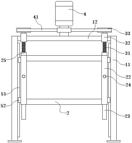
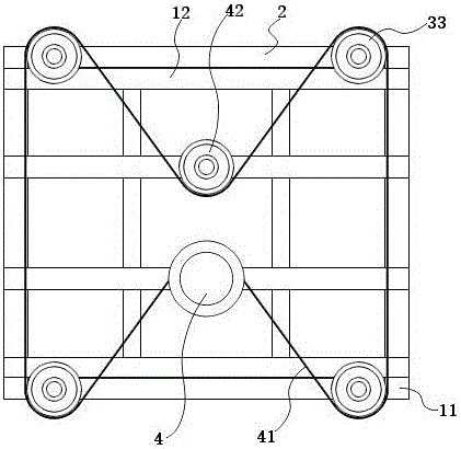
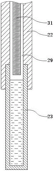
[0019] Such as figure 1 As shown, a box foaming equipment driven by an upper-mounted screw rod includes a frame, a box frame 2, a screw rod 31 and a motor 4. The frame includes a vertical column 11 and a top platform 12 on the top of the column 11 . There are four columns 11 in a square layout, and the columns 11 are located at the four corners of the square. Case frame 2 is used for installing foam case, or is exactly foam case itself. The four corners of the box frame 2 are provided with four cavity columns 22 . There are four screw mandrels 31, which are suspended on the top platform 12 by screw mandrel bearings 32. The lower end of the screw mandrel 31 is suspended to form a free end. The positions of the four screw rods 31 correspond to the four cavity columns 22 one by one. A wire sleeve 25 engaged with the screw rod 31 is provided on the cavity c...


PUM


Abstract

The invention discloses upper box body foaming equipment driven by screw rods. The upper box body foaming equipment comprises a rack, a box frame, the screw rods and a motor, wherein the motor is arranged on a top platform of the rack; the number of the screw rods is four; and the four screw rods are suspended on the top platform through screw rod bearings and are connected with the motor through a driving mechanism arranged on the top platform. Four cavity columns are arranged at four corners of the box frame and are provided with screw taps connected with the screw rods; a cavity is arranged in each cavity column, and a lubricating oil tank is arranged below each cavity column; the cavity in each cavity column communicates with the corresponding lubricating oil tank; the screw rods penetrate into the corresponding cavities and the lower ends of the screw rods can be immersed in lubricating oil of the corresponding lubricating oil tanks when the box frame ascends; and a lifting guide mechanism is arranged between the box frame and the rack.

Description

technical field [0001] The invention relates to box body foaming equipment, in particular to lifting equipment for a foaming box in the box body foaming equipment. Background technique [0002] In traditional box foaming equipment, the foaming box (foaming platform) usually uses a hydraulic mechanism as the power system for the lifting of the foaming box. For example, the box foaming equipment disclosed in the patent document CN104227907A adopts a hydraulic lifting mechanism. Also have to adopt screw mandrel screw sleeve as driving mode, as disclosed box body foaming equipment of CN204749097U has adopted screw mandrel screw sleeve, screw mandrel connects motor, then is driven by motor to rotate screw mandrel, through the screw thread engagement of screw mandrel screw sleeve Drive the foam box up and down. Under this screw mandrel thread sleeve lifting mode, the screw mandrel is erected on the ground, and the motor is also on the ground. There are some disadvantages in this...

Claims


Application Information

Patent Timeline
IPC IPC(8): B66F7/00B66F7/28F16N7/28F16N7/18
CPCB66F7/00B66F7/28F16N7/18F16N7/28
Inventor 钱思圣段宗军
Owner 江苏天辰智能装备有限公司
Why Eureka
Try Eureka