
Blast-furnace high-blast temperature energy-saving emission-reduction combined system

A technology of energy saving and emission reduction, combined system, applied in blast furnace details, blast furnace, blast furnace parts and other directions, can solve the problems of poor energy saving effect, pollution, emission, etc., achieve simple structure, improve energy saving and emission reduction effect, increase The effect of high air temperature effect

Active Publication Date: 2016-10-26
秦皇岛佰工钢铁有限公司
View PDF5 Cites 1 Cited by
  • Summary
  • Abstract
  • Description
  • Claims
  • Application Information

AI Technical Summary

Problems solved by technology

[0002] With the rapid growth of the modern economy, the construction of blast furnace ironmaking has made great achievements, but it has also paid a huge price for the destruction of resources and the environment. The contradiction between the two has become increasingly acute. In modern blast furnace ironmaking, high blast temperature is a A common energy-saving technology. In the current blast furnace ironworks, it often happens that the temperature of the gas meets the requirements when it is just preheated, but part of the heat is dissipated during transportation, causing the preheated gas to enter the combustion furnace and fail to meet the requirements. In this way, the energy-saving effect becomes worse. A certain amount of toxic gas carbon monoxide and some dust remain in the mixed smoke collected by the combustion furnace of the existing blast furnace ironworks. Such mixed smoke is discharged into the air and will cause serious pollution.

Method used


Image

  • Blast-furnace high-blast temperature energy-saving emission-reduction combined system

Examples


specific Embodiment approach

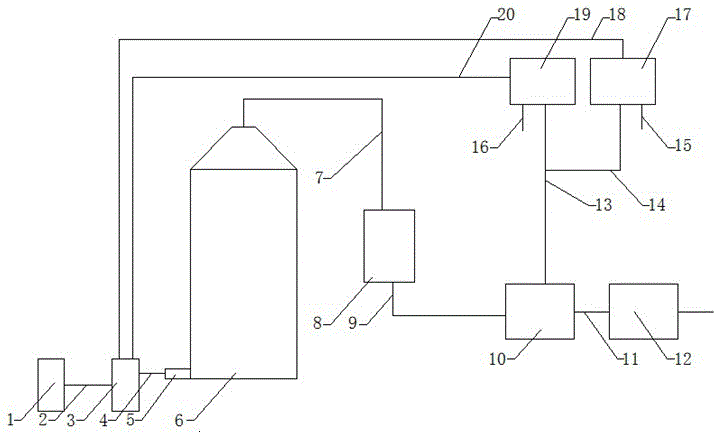
[0019] Specific embodiments: when the combustion furnace 6 is working, it will produce mixed smoke with heat, and these mixed smoke with heat will enter the secondary combustion device 8 through the mixed smoke channel pipe 7 at the top of the combustion furnace 6, and these mixed smoke with heat will enter the secondary combustion device 8. The mixed smoke is undergoing secondary combustion in the secondary combustion device 8, which can convert the toxic carbon monoxide in the mixed smoke into nontoxic carbon dioxide, and can also increase the heat of the mixed smoke.

[0020] After the secondary combustion, the mixed smoke passes through the mixed smoke outlet pipe 9, reaches the gas heat exchanger 10, and is transformed by the gas heat exchanger 10, and the mixed smoke forms air and exhaust gas with heat.

[0021] The waste gas in the gas heat exchanger 10 reaches the waste gas dedusting device 12 through the waste gas outlet pipe 11. After the waste gas is treated by the w...


PUM


Abstract

The invention provides a blast-furnace high-blast temperature energy-saving emission-reduction combined system. The system comprises a waste residue waste heat generating device, a heat supplement device, a combustor, a combustion furnace, a secondary combustor, a gas heat exchanger and an exhaust gas dust collector. The waste residue waste heat generating device is connected to the heat supplement device through a power supply wire, the heat supplement device is connected to the combustor through a mixed gas channel pipe, the right end of the combustor is connected to the combustion furnace, the mixed gas channel pipe of the combustion furnace is connected to the secondary combustor, the secondary combustor is connected to the gas heat exchanger through a mixed smoke outlet pipe, the gas heat exchanger is connected to the exhaust gas dust collector through an exhaust gas outlet pipe, and the upper end of the heat supplement device is connected to a gas preheating outlet pipe and a combustion air preheating outlet pipe. The system has a simple structure, improves high-blast temperature effects and improves energy-saving and emission-reduction effects.

Description

technical field [0001] The invention is an energy-saving and emission-reduction combined system for high blast furnace blast temperature, which belongs to the technical fields of energy-saving and emission reduction and iron and steel smelting equipment. Background technique [0002] With the rapid growth of the modern economy, the construction of blast furnace ironmaking has made great achievements, but it has also paid a huge price for the destruction of resources and the environment. The contradiction between the two has become increasingly acute. In modern blast furnace ironmaking, high blast temperature is a A common energy-saving technology. In the current blast furnace ironworks, it often happens that the temperature of the gas meets the requirements when it is just preheated, but part of the heat is dissipated during transportation, causing the preheated gas to enter the combustion furnace and fail to meet the requirements. In this way, the energy-saving effect will ...

Claims


Application Information

Patent Timeline
Patent Type & Authority Applications(China)
IPC IPC(8): C21B9/00C21B9/14C21B9/10
CPCC21B9/00C21B9/10C21B9/14
Inventor 柴永朋李朋飞柴名
Owner 秦皇岛佰工钢铁有限公司
Learn More