Wave energy power generation device

A technology for power generation and wave energy, applied in electromechanical devices, ocean energy power generation, electrical components, etc., can solve the problems of high delivery and recovery costs, difficult dynamic sealing, low work efficiency, etc., to reduce delivery and recovery costs and improve reliability. The effect of sex, lead convenience

Active Publication Date: 2016-10-26
INST OF ELECTRICAL ENG CHINESE ACAD OF SCI
View PDF11 Cites 5 Cited by
  • Summary
  • Abstract
  • Description
  • Claims
  • Application Information

AI Technical Summary

Problems solved by technology

[0011] The purpose of the present invention is to overcome the shortcomings of the existing wave energy generation device, such as complex structure, poor versatility, low work efficiency, poor reliability, difficult dynamic sealing, high cost of delivery and recovery, and propose a wave energy generation device

Method used


Image

  • Wave energy power generation device
  • Wave energy power generation device
  • Wave energy power generation device

Examples


Embodiment Construction

[0028] The present invention will be further described below in conjunction with the drawings and specific embodiments.

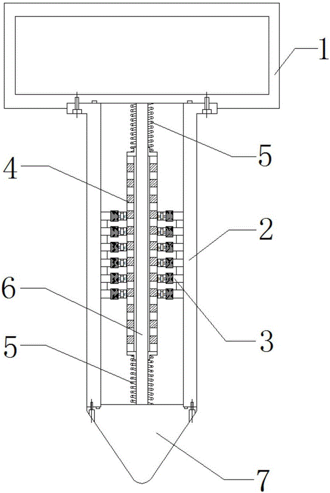
[0029] Such as figure 1 As shown, the wave energy power generation device of the present invention includes a float 1, a casing 2, a stator 3, a mover 4, a spring 5, a mover slide 6 and a tapered end cover 7. The float 1 and the tapered end cover 7 are located at the two ends of the casing 2 and form a sealed cavity with the casing 2. The stator 3, the mover 4, the spring 5 and the mover slide 6 are sealed inside the casing 2.

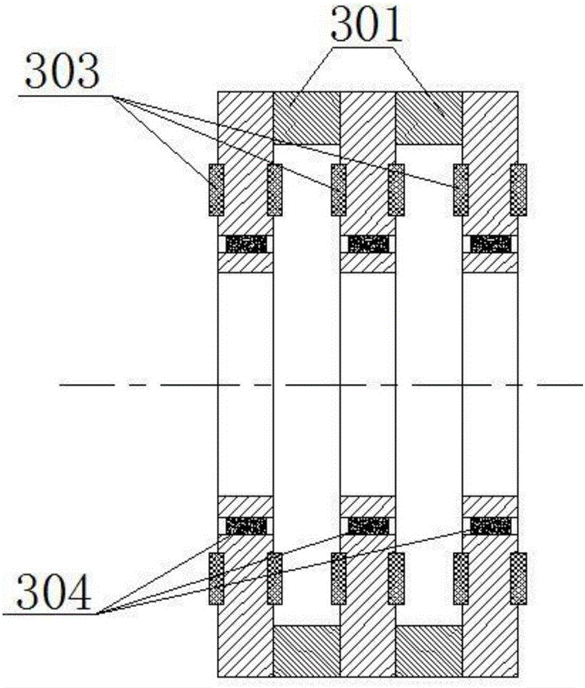
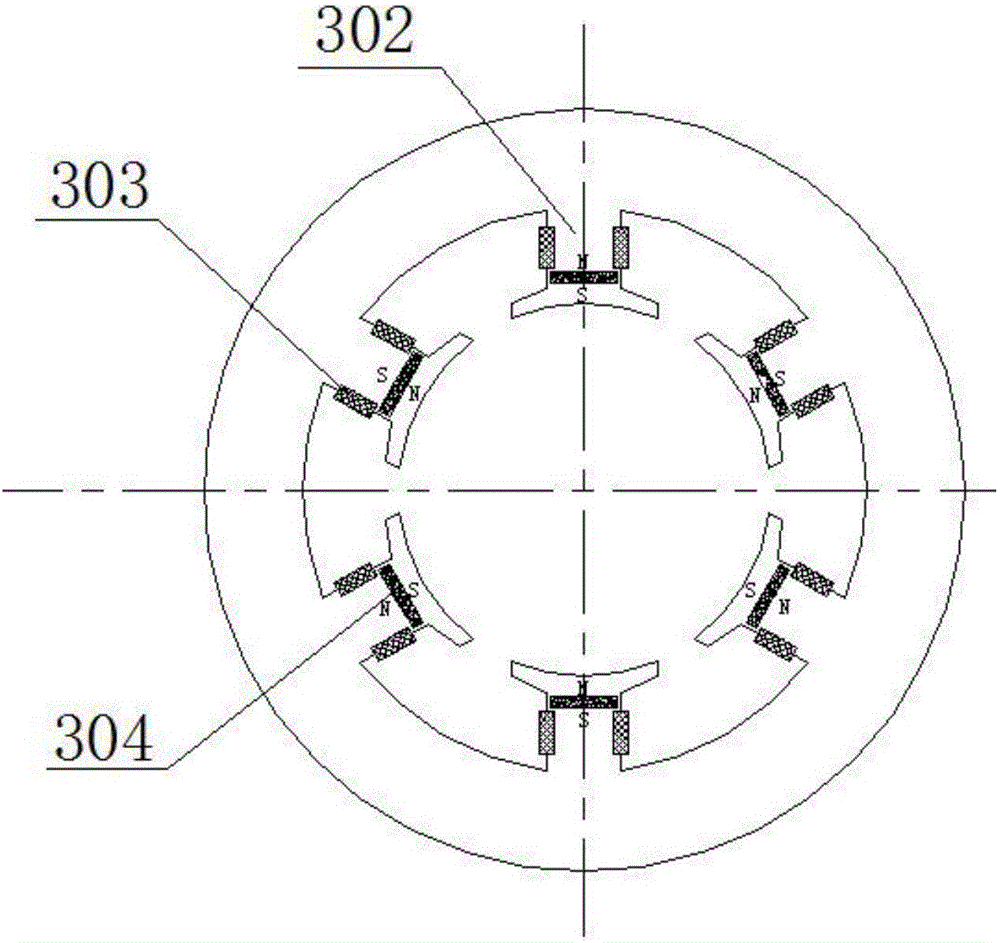
[0030] Such as figure 1 Or as shown in FIG. 2, the stator 3 has a cylindrical structure, which is formed by alternately stacking a plurality of stator units and stator magnetic isolation rings 301 with the same thickness in the axial direction. A certain number of stator teeth 302 are evenly distributed inside the stator unit, and coils 303 are wound on the stator teeth. A square hole is opened on the top of the stator tooth 302, and a ...


PUM


Abstract

The invention provides a wave energy power generation device. A floater and a conical end cover of the wave energy power generation device are located at the two ends of a machine shell, and the floater, the conical end cover and the machine shell form a sealed cavity. A stator, a rotor, springs and a rotor sliding rail are sealed in the machine shell. The stator is cylindrical, located on the inner side of the machine shell and formed by alternately stacking a plurality of stator units which are the same in thickness and a plurality of stator magnetism isolating rings which are the same in thickness in the axial direction. Stator teeth are uniformly distributed on the inner side of each stator unit. A coil is wound on each stator tooth. A square hole is formed in the top of each stator tooth. A square radially magnetized permanent magnet is embedded in each square hole. The magnetic poles of the permanent magnets are alternately arranged in the circumferential direction. The rotor is cylindrical, located on the inner side of the stator and formed by alternately stacking a plurality of rotor magnetism conducting rings which are the same in thickness and a plurality of rotor magnetism isolating rings which are the same in thickness in the axial direction. The rotor and the springs are installed on the rotor sliding rail. The rotor can slide up and down along the rotor sliding rail. The rotor sliding rail and the machine shell are concentric and coaxial, and the two ends of the rotor sliding rail are fixed to the floater and the conical end cover correspondingly. The springs are located on the two sides of the rotor and connected with the floater and the conical end cover correspondingly.

Description

Technical field [0001] The invention relates to a wave energy power generation device. Background technique [0002] Wave energy is a kind of renewable clean energy with abundant reserves and wide distribution. According to estimates by the World Energy Association, the amount of ocean wave energy resources in the world is more than 2TW, which is equivalent to the sum of all other forms of energy in the world. If 0.1% of this is converted into electrical energy, it will exceed the current worldwide use. 5 times the power. Therefore, the development and utilization of wave energy has broad application prospects. [0003] At present, wave energy power generation devices can be divided into two major categories, namely mechanical and direct drive. [0004] Mechanical wave energy power generation devices generally include three-level energy conversion. The first-level energy conversion mechanism directly interacts with waves to convert wave energy into device kinetic energy or water p...

Claims


Application Information

Patent Timeline
Patent Type & Authority Applications(China)
IPC IPC(8): F03B13/14H02K35/02
CPCF03B13/14F05B2220/706H02K35/02Y02E10/30
Inventor 黄元峰徐松艾程柳邱书恒王海峰
Owner INST OF ELECTRICAL ENG CHINESE ACAD OF SCI
Why Eureka
Try Eureka