Single-rod magnetorheological elastomer damper

A magneto-rheological elastomer and a single rod technology, which is applied in the field of dampers, can solve problems such as failure of magnetorheological dampers, difficulties in dynamic sealing, and performance degradation of magnetorheological dampers.

Inactive Publication Date: 2012-07-04
谭晓婧
View PDF7 Cites 0 Cited by
  • Summary
  • Abstract
  • Description
  • Claims
  • Application Information

AI Technical Summary

Problems solved by technology

[0002] The existing single-rod magnetorheological damper mainly adopts the structure of working cylinder, piston and piston rod, and the working cylinder is also filled with magnetorheological fluid. This kind of magnetorheological damper is driven by the piston rod The reciprocating motion in the working cylinder is used to generate damping force. In order to prevent the magnetorheological fluid in the working cylinder from being taken out of the working cylinder with the piston rod, a sealing device is usually used between the working cylinder and the piston rod to solve the dynamic problem of the piston rod. Sealing problem, since the magnetorheological fluid is a mixture of fine powders containing various components in mineral oil, it is very difficult to dynamically seal it. Once the leakage of the magnetorheological fluid occurs, it will cause the magnetorheological damping The performance of the magneto-rheological damper is degraded, and the magneto-rheological damper is completely invalid. Therefore, the dynamic sealing problem of the piston rod has become the main obstacle in the industry to improve the service life of the magnetorheological damper.

Method used


Image

  • Single-rod magnetorheological elastomer damper
  • Single-rod magnetorheological elastomer damper
  • Single-rod magnetorheological elastomer damper

Examples


Embodiment Construction

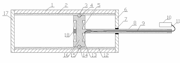
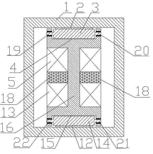
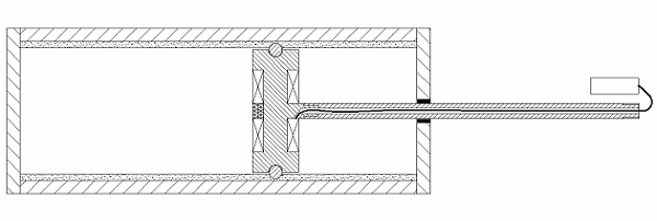
[0016] The structure of the present invention is described in detail below in conjunction with accompanying drawing:

[0017] see figure 1 and figure 2 , which is a specific structure of the present invention, a single-rod magneto-rheological elastomer damper, which includes: a damping rod 8 made of non-magnetic material, a damping block 16 made of magnetic material, a Two damping rollers 3 and 14 are made of magnetic material, and the working cylinder 1 is made of magnetically conductive material; the cross section of the inner cavity of the working cylinder 1 is rectangular, and baffle plates 6 and 17 are fixed at both ends of the working cylinder 1, wherein: the baffle plate There is a hole in the middle of 6, and a sliding bearing 7 is fixed in the hole, and a layer of magnetorheological elastomer 2 and 12 is fixed on the surface of the two short sides in the working cylinder 1; the section of the damping block 16 is I-shaped, and The middle part of the damping block 16...


PUM


Abstract

The invention discloses a single-rod magnetorheological elastomer damper. The single-rod magnetorheological elastomer damper comprises a damper rod, a damper block, two damper rollers and a working cylinder, wherein the cross section of the inner cavity of the working cylinder is of rectangle; baffle plates are both fixed at two ends of the working cylinder, the middle of one of the baffle plates is provided with a hole, and a sliding bearing is fixed in the hole; a layer of magnetorheological elastomer is fixed on the surfaces of the two short edges in the working cylinder; the cross section of the damper block is of an I shape; an excitation coil is wound in the middle of the damper block; a semicircular groove is arranged on the middle parts of the two ends of the damper block respectively, and the axis line of the groove is perpendicular to the axis line of the damper rod; the diameter of the groove is larger than the diameter of each damper roller; the damper rollers are installed in the semicircular groove at the two ends of the damper block; one end of the damper rod and the damper block are fixed; and the other end of the damper rod extends out of the working cylinder through the sliding bearing on the baffle plate at one end of the working cylinder.

Description

technical field [0001] The invention belongs to a damper, in particular to a single-rod magneto-rheological elastomer damper. Background technique [0002] The existing single-rod magnetorheological damper mainly adopts the structure of working cylinder, piston and piston rod, and the working cylinder is also filled with magnetorheological fluid. This kind of magnetorheological damper is driven by the piston rod The reciprocating motion in the working cylinder is used to generate damping force. In order to prevent the magnetorheological fluid in the working cylinder from being taken out of the working cylinder with the piston rod, a sealing device is usually used between the working cylinder and the piston rod to solve the dynamic problem of the piston rod. Sealing problem, since the magnetorheological fluid is a mixture of fine powders containing various components in mineral oil, it is very difficult to dynamically seal it. Once the leakage of the magnetorheological fluid ...

Claims


Application Information

Patent Timeline
Patent Type & Authority Applications(China)
IPC IPC(8): F16F9/53
Inventor 谭和平谢宁刘强谭晓婧
Owner 谭晓婧
Why Eureka
Try Eureka