
Large-torque U-shaped hydraulic slewing mechanism

A technology of slewing mechanism and high torque, applied in the direction of fluid pressure actuating device, etc., can solve the problems of large axial structure size, unusable installation space, limited promotion, etc., and achieve the effect of small shape and structure size

Active Publication Date: 2016-10-26
无锡通美机械科技有限公司
View PDF6 Cites 0 Cited by
  • Summary
  • Abstract
  • Description
  • Claims
  • Application Information

AI Technical Summary

Problems solved by technology

[0002] At present, large-scale flipping arms and high-torque slewing mechanisms are used in industry. The rapid development of industrial robots has made the application of high-torque slewing mechanisms more extensive. There are two rotary methods, but both methods have shortcomings. The radial structure size of the spiral hydraulic rotary oil cylinder is small, but the axial structure size is too large, and sometimes it cannot be used due to the limited installation space.
Rack rotary oil cylinder, because the power rack is a linear structure, the shape of the equipment is elongated or H-shaped, and the installation size of the shape structure is too large, which increases the radius of gyration and production cost, and the installation is troublesome or the site is limited, which limits the promotion.

Method used


Image

  • Large-torque U-shaped hydraulic slewing mechanism
  • Large-torque U-shaped hydraulic slewing mechanism

Examples


Embodiment

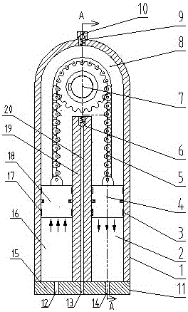
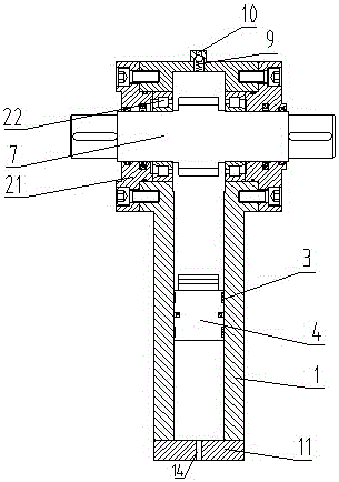
[0014] Embodiment: The high-torque U-shaped hydraulic slewing mechanism as shown in the figure includes a cylinder body 1, which is U-shaped with an opening downward. The upper end of the cylinder body 1 is provided with an exhaust hole 10 for exhausting A one-way valve 9 for deflation is provided at the hole 10 . The upper part of the cylinder body 1 is a hydraulic oil chamber 8, the two ends of the hydraulic oil chamber 8 are provided with end caps 21, and the end caps 21 are provided with bearings 22, and a rotary shaft 7 is installed between the bearings 22, and the rotary shaft The middle part of 7 is sprocket. A partition 19 is arranged in the middle of the lower part in the cylinder body 1, and an oil inlet passage 20 is arranged in the middle of the partition 19. The lower end of the oil inlet passage 20 is an oil inlet hole 13, and the upper end of the oil inlet passage 20 is located at the hydraulic pressure. An oil discharge hole is arranged in the oil chamber 8 at...


PUM


Abstract

The invention discloses a large-torque U-shaped hydraulic slewing mechanism. The large-torque U-shaped hydraulic slewing mechanism comprises a cylinder body, wherein the cylinder body is U-shaped with the opening facing downwards; an exhaust hole is formed in the upper end of the cylinder body; the upper part of the cylinder body is a hydraulic oil cavity; a rotating shaft is arranged in the hydraulic oil cavity; a partition plate is arranged in the position, in the middle of the lower part, inside the cylinder body; an oil inlet channel is arranged in the middle of the partition plate; the partition plate divides the lower part of the cylinder body into a left cylinder body and a right cylinder body; a left piston and a right piston are respectively arranged inside the left cylinder body and the right cylinder body; a chain is connected between the left piston and the right piston; the chain is wound on a chain gear in the middle of the rotating shaft; the lower end parts of the left cylinder body and the right cylinder body are respectively provided with a left end cover and a right end cover; and a left oil hole and a right oil hole are respectively formed in the left end cover and the right end cover. According to the large-torque U-shaped hydraulic slewing mechanism, through the hydraulic transmission of the hydraulic oil in the U-shaped cylinder body, the left piston and the right piston move up and down in the left cylinder body and the right cylinder body, and the chain connected between the left piston and the right piston drives the rotating shaft to rotate.

Description

technical field [0001] The invention belongs to the field of slewing drive, in particular to a U-shaped hydraulic slewing mechanism with high torque. Background technique [0002] At present, large-scale turning arms and high-torque slewing mechanisms are used in industry. The rapid development of industrial robots has made the application of high-torque slewing mechanisms more extensive. There are two kinds of rotation methods, but both methods have shortcomings. The radial structure size of the spiral hydraulic rotary oil cylinder is small, but the axial structure size is too large, and sometimes it cannot be used due to the limited installation space. Rack rotary oil cylinder, because the power rack is a linear structure, the appearance of the equipment is elongated or H-shaped, and the installation size of the outer structure is too large, which increases the radius of gyration and production cost, and the installation is troublesome or the site is limited, which limits ...

Claims


Application Information

Patent Timeline
Patent Type & Authority Applications(China)
IPC IPC(8): F15B15/08
CPCF15B15/14
Inventor 傅国俊崔书林
Owner 无锡通美机械科技有限公司
Learn More