Measurement controller and measurement control method for smelter

A controller and furnace technology, used in furnace control devices, furnace safety devices, furnaces, etc., can solve the problems of inability to test the temperature of the tuyere whirling zone, gas composition, mineral material chemical composition, and inability to control the blasting of the charge, and reduce production costs. , the effect of improving production efficiency

Active Publication Date: 2016-10-26
宗品禾
View PDF4 Cites 5 Cited by
  • Summary
  • Abstract
  • Description
  • Claims
  • Application Information

AI Technical Summary

Problems solved by technology

[0002] At present, my country's metallurgical blast furnace is under high pressure and high temperature, that is, 2500 ℃, 4-5MPa, during the production process of coal powder injection, because the measurement port is in the process of opening and closing, and the furnace charge cannot be controlled. Therefore, it is impossible to test the temperature and There is an urgent need for a safe and effective measuring device and measuring method for the gas composition and the chemical composition of the ore in the swing area to realize online measurement

Method used


Image

  • Measurement controller and measurement control method for smelter
  • Measurement controller and measurement control method for smelter

Examples


Embodiment 1

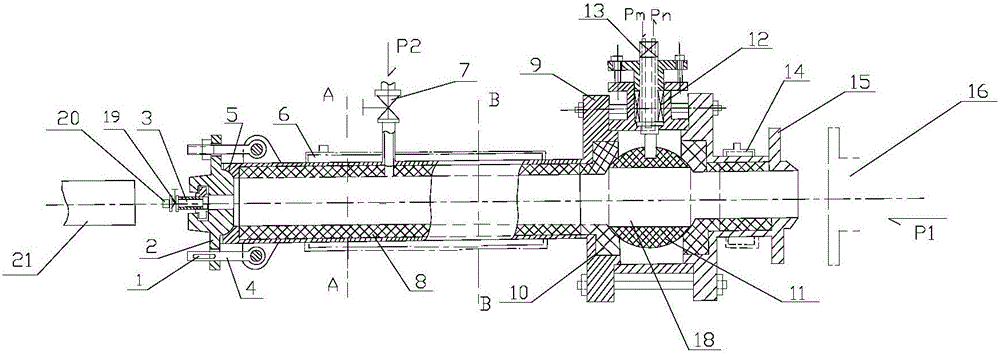
[0018] The structure of this embodiment is as figure 1 As shown, a furnace measurement controller includes a high temperature resistant controller body. The two ends of the controller body are respectively a measuring rod channel extending to the left and a measuring channel extending to the right. The left side of the controller body reaches the measuring rod A left housing 9 is arranged outside the channel, a right housing 15 is provided from the right side of the controller body to the outside of the measuring channel, a bushing 8 is provided on the inner wall of the left and right housings, an end cover 2 is provided at the end of the measuring rod channel, and the measuring channel is connected The position of the furnace to be measured, the center of the end cover 2 is provided with an observation channel, the bottom of the end cover 2 forms an arc-shaped seal with the shell at the entrance of the measuring rod channel, and the middle part of the end cover 2 has a symmetr...

Embodiment 2

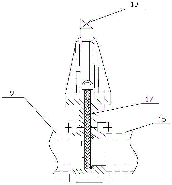
[0023] The structure of this embodiment is roughly the same as that of Embodiment 1, as figure 2 As shown, the difference is that a valve plate 17 is placed in the middle of the main body of the controller, and the valve plate 17 is fixedly connected with the bottom of the control rod 13. The valve plate 17 is located in the control chamber 18. When the pressure is 0.1Mpa-0.8Mpa, the The on-off operation of the control chamber is completed by facing the sliding valve plate, specifically: when the control rod 13 is in the rising position, it drives the valve plate 17 to rise, and the control chamber 18 is the entire chamber; when the control rod 13 is in the down position, it drives the The valve plate 17 divides the control chamber 18 into left and right chambers.


PUM


Abstract

The invention relates to a measurement device and a measurement method for a smelter, in particular to a measurement controller and a measurement control method for the smelter, and belongs to the technical field of medical equipment. The measurement controller structurally comprises a high-temperature-resistant controller body; a measurement rod passage extending leftwards and a measurement passage extending rightwards are formed in the two ends of the controller body correspondingly; a left outer shell is arranged from the left side of the controller body to the outside of the measurement rod passage; a right outer shell is arranged from the right side of the controller body to the outside of the measurement passage; the inner walls of the left outer shell and the right outer shell are provided with linings; an end cover is arranged at the end of the measurement rod passage; and the measurement passage is connected with a to-be-measured position of the smelter. It is ensured that high-temperature and high-pressure gas in the smelter does not leak while gas and charge in the smelter are taken out during blast furnace production.

Description

technical field [0001] The invention relates to a furnace measurement device and a measurement method, in particular to a furnace measurement controller and a measurement control method, belonging to the technical field of mechanical equipment. Background technique [0002] At present, my country's metallurgical blast furnace is under high pressure and high temperature, that is, 2500 ° C, 4-5 MPa, during the production process of pulverized coal injection, because the measurement port is in the process of opening and closing, and the furnace charge cannot be controlled. Therefore, it is impossible to test the temperature and There is an urgent need for a safe and effective measuring device and measuring method for the gas composition and the chemical composition of the ore in the swing area to realize on-line measurement. Contents of the invention [0003] The object of the present invention is to propose a furnace measurement controller and a measurement control method for...

Claims


Application Information

Patent Timeline
Patent Type & Authority Applications(China)
IPC IPC(8): F27D19/00F27D21/00C21B7/24
CPCC21B7/24F27D19/00F27D21/00F27D2019/0003F27D2019/0012F27D2019/0018F27D2021/0057
Inventor 宗品禾
Owner 宗品禾
Why Eureka
Try Eureka