A furnace measurement controller and measurement control method
A technology for controllers and furnaces, which is applied in the direction of furnace control devices, furnace safety devices, furnaces, etc., which can solve the problems of uncontrollable charge ejection, inability to test the temperature, gas composition, and mineral material chemical composition in the tuyere swirl area, etc., to reduce production costs , the effect of improving production efficiency
- Summary
- Abstract
- Description
- Claims
- Application Information
AI Technical Summary
Problems solved by technology
Method used
Image
Examples
Embodiment 1
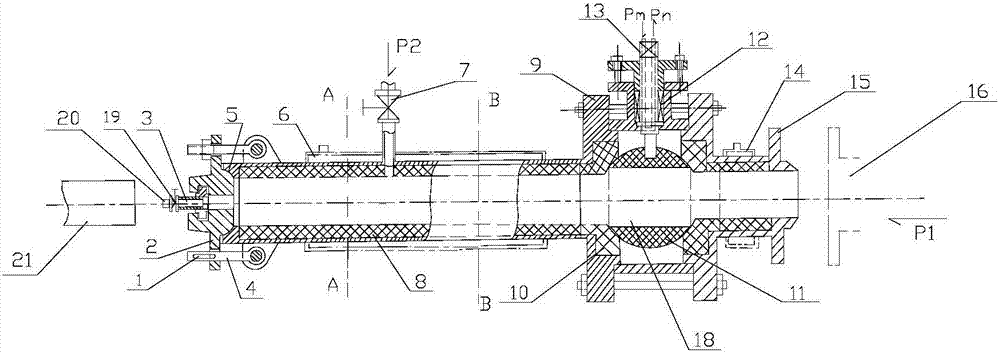
[0018] The structure of this embodiment is as figure 1 As shown, a furnace measurement controller includes a high temperature resistant controller body. The two ends of the controller body are respectively a measuring rod channel extending to the left and a measuring channel extending to the right. The left side of the controller body reaches the measuring rod A left housing 9 is arranged outside the channel, a right housing 15 is provided from the right side of the controller body to the outside of the measuring channel, a bushing 8 is provided on the inner wall of the left and right housings, an end cover 2 is provided at the end of the measuring rod channel, and the measuring channel is connected The position of the furnace to be measured, the center of the end cover 2 is provided with an observation channel, the bottom of the end cover 2 forms an arc-shaped seal with the shell at the entrance of the measuring rod channel, and the middle part of the end cover 2 has a symmetr...
Embodiment 2
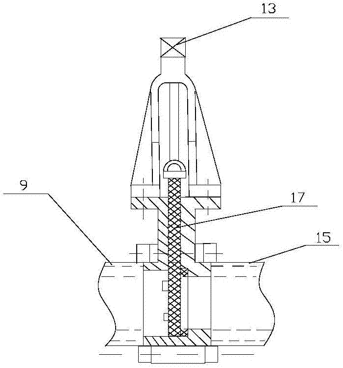
[0023] The structure of this embodiment is roughly the same as that of Embodiment 1, as figure 2 As shown, the difference is that a valve plate 17 is placed in the middle of the main body of the controller, and the valve plate 17 is fixedly connected with the bottom of the control rod 13. The valve plate 17 is located in the control chamber 18. When the pressure is 0.1Mpa-0.8Mpa, the The on-off operation of the control chamber is completed by facing the sliding valve plate, specifically: when the control rod 13 is in the rising position, it drives the valve plate 17 to rise, and the control chamber 18 is the entire chamber; when the control rod 13 is in the down position, it drives the The valve plate 17 divides the control chamber 18 into left and right chambers.
PUM
 Abstract
Description
Claims
Application Information
 - R&D
- Intellectual Property
- Life Sciences
- Materials
- Tech Scout
- Unparalleled Data Quality
- Higher Quality Content
- 60% Fewer Hallucinations
Browse by: Latest US Patents, China's latest patents, Technical Efficacy Thesaurus, Application Domain, Technology Topic, Popular Technical Reports.
© 2025 PatSnap. All rights reserved.Legal|Privacy policy|Modern Slavery Act Transparency Statement|Sitemap|About US| Contact US: help@patsnap.com


