
Step voltage calculation method under symmetrical double-core phase shift transformer load condition

A phase-shifting transformer and voltage calculation technology, applied in the field of transformer manufacturing, can solve the problems of load current and load voltage phase difference variation, inability to realize on-load tap-changer economically and reliably, and various design parameters.

Active Publication Date: 2016-10-26
CHINA ELECTRIC POWER RES INST +3
View PDF8 Cites 2 Cited by
  • Summary
  • Abstract
  • Description
  • Claims
  • Application Information

AI Technical Summary

Problems solved by technology

At this stage, the determination of the stage voltage of the on-load tap changer in the phase-shifting transformer is firstly calculated under no-load conditions, and then the maximum stage voltage is determined according to a certain experience margin. Compared with ordinary transformers, the phase-shifting The structure of the transformer is complex, the design parameters are various, and there are two ways of leading regulation and lagging regulation, the magnitude of the load current and the phase difference with the load voltage vary greatly
Therefore, there is a lack of necessary theoretical research on the size of the step voltage and its influencing factors under load conditions, and the selection of on-load tap-changers cannot be realized economically and reliably according to the existing methods.

Method used


Image

  • Step voltage calculation method under symmetrical double-core phase shift transformer load condition
  • Step voltage calculation method under symmetrical double-core phase shift transformer load condition
  • Step voltage calculation method under symmetrical double-core phase shift transformer load condition

Examples


Embodiment Construction

[0034] Exemplary embodiments of the present invention will now be described with reference to the drawings; however, the present invention may be embodied in many different forms and are not limited to the embodiments described herein, which are provided for the purpose of exhaustively and completely disclosing the present invention. invention and fully convey the scope of the invention to those skilled in the art. The terms used in the exemplary embodiments shown in the drawings do not limit the present invention. In the figures, the same units / elements are given the same reference numerals.

[0035] Unless otherwise specified, the terms (including scientific and technical terms) used herein have the commonly understood meanings to those skilled in the art. In addition, it can be understood that terms defined by commonly used dictionaries should be understood to have consistent meanings in the context of their related fields, and should not be understood as idealized or over...


PUM


Abstract

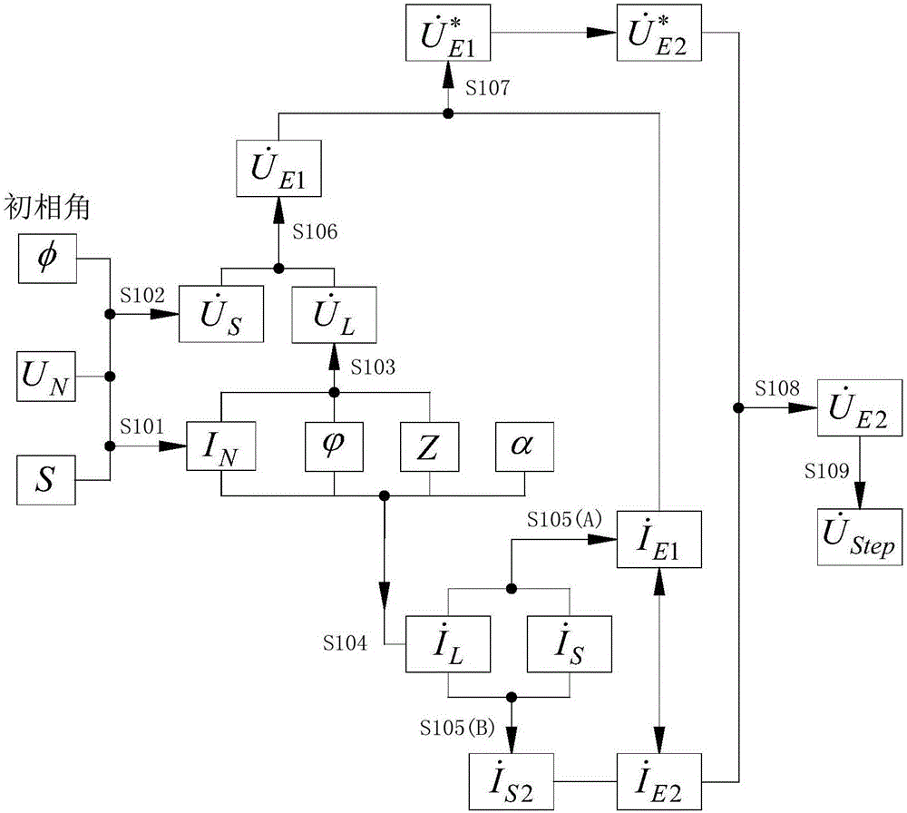
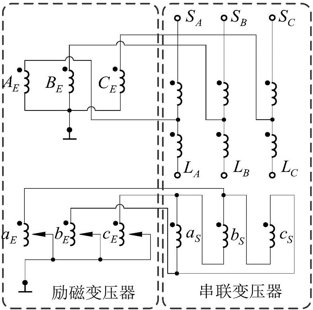
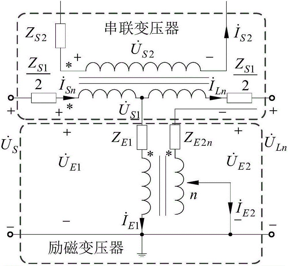
The invention relates to a step voltage calculation method under a symmetrical double-core phase shift transformer load condition. The calculation method comprises a step of determining rated current IN and series transformer power supply side voltage Us according to the rated pass capacitance S and the rated voltage UN of a phase-shifting transformer, a step of determining series connection transformer load side voltage UL according to the rated current IN,overall leakage impedance Z and power factor angle phi, and combined with the phase shift angle in an empty load, determining series connection transformer power supply side current Is and load side current IL, a step of determining excitation transformer primary side current IE1 and second side current IE2 according to the series connection transformer power supply side current Is and the load side current IL, a step of determining excitation transformer primary side voltage UE1 according to the series transformer power supply side voltage Us, the load side voltage UL excitation transformer primary side current IE1, and secondary side current IE2, and thus determining excitation transformer secondary side voltage UE2, and a step of determining a load tap-changer level voltage Ustep according to the excitation transformer secondary side voltage UE2. The invention provides a method for calculating overall leakage impedance Zn and a phase shift angle an in an empty load in a selected n gear of the phase shift transformer.

Description

technical field [0001] The invention relates to the technical field of transformer manufacturing, and more specifically, relates to a method for calculating the voltage of an on-load tap changer stage of a symmetrical double-core phase-shifting transformer under load conditions. Background technique [0002] As a method of eliminating overload and controlling the active power flow of the system, the phase-shifting transformer has been widely concerned by experts at home and abroad because of its advantages of convenient operation and little additional impact on the power system. The on-load tap-changer is a key component for adjusting the voltage phase-shifting angle of the phase-shifting transformer. The determination of its key technical parameters and reasonable selection will directly affect the design and reliable operation of the phase-shifting transformer. At this stage, the determination of the stage voltage of the on-load tap changer in the phase-shifting transforme...

Claims


Application Information

Patent Timeline
IPC IPC(8): G01R19/00
Inventor 高飞李金忠刘欣王利桐郭锐关健昕张书琦李博程涣超赵志刚刘雪丽汤浩王健一孙建涛贾鹏飞遇心如吴超仇宇舟汪可赵晓宇申泽军徐征宇
Owner CHINA ELECTRIC POWER RES INST
Learn More