Three-phase electric rectification circuit and three-phase electric rectification circuit time sequence control method

A technology of rectification circuit and three-phase alternating current, applied in the direction of converting AC power input into DC power output, electrical components, output power conversion devices, etc., can solve problems such as switch damage, avoid switch damage, improve reliability, Avoid the effect of inrush current

Inactive Publication Date: 2016-10-26
HISENSE (SHANDONG) AIR CONDITIONING CO LTD
View PDF7 Cites 5 Cited by
  • Summary
  • Abstract
  • Description
  • Claims
  • Application Information

AI Technical Summary

Problems solved by technology

[0004] The application provides a three-phase electric rectification circuit and a timing control method for the three-phase electric rectification circuit, which solves the technical problem that the current inrush current in the existing three-phase electric rectification circuit causes damage to the switch

Method used


Image

  • Three-phase electric rectification circuit and three-phase electric rectification circuit time sequence control method
  • Three-phase electric rectification circuit and three-phase electric rectification circuit time sequence control method
  • Three-phase electric rectification circuit and three-phase electric rectification circuit time sequence control method

Examples


Embodiment Construction

[0019] The specific implementation manners of the present application will be described in further detail below in conjunction with the accompanying drawings.

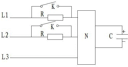
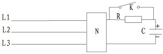
[0020] The purpose of this application is to propose a three-phase electric rectification circuit to solve the problem that the voltage at both ends of the electrolytic capacitor after charging will be lower than the three-phase electric rectification voltage due to the voltage division effect of the current-limiting resistor in the existing three-phase electric rectification circuit. When the circuit switch is closed, a large inrush current will be generated to cause damage to the switch.

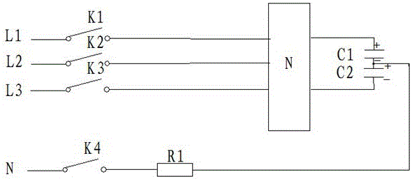
[0021] Such as image 3 As shown, the present application proposes a three-phase rectification circuit, including a three-phase AC input, a rectifier bridge N and an electrolytic capacitor; the three-phase AC output includes a first-phase AC input L1, a second-phase AC input L2 and a third-phase AC Input L3; an electrolytic capaci...


PUM


Abstract

The invention discloses a three-phase electric rectification circuit and a three-phase electric rectification circuit time sequence control method, with the object to address the problem that the impulse current in a three-phase electric rectification circuit causes damage to switches. The three-phase electric rectification circuit comprises a three-phase AC input circuit, a rectifier bridge, electrolytic capacitors, a control circuit and a zero line. A first electrolytic capacitor and a second electrolytic capacitor are in series connection between the positive pole and the negative pole of the rectifier bridge DC output. The zero line is connected to the connection parts of the first electrolytic capacitor and the second electrolytic capacitor through a fourth switch and a first current-limiting resistor. The three-phase AC input circuit is connected to the bridge rectifier through a first switch, a second switch, and a third switch respectively. The control circuit, T1 after three-phase AC power is input, controls one of the three switches and the fourth switch to close. When the electrolytic capacitors are charged full, the fourth switch is turned off and the other two remaining switches of the three switches are also closed. By charging the electrolytic capacitors in advance to make sure that the voltage at both ends of the electrolytic capacitors is higher than three-phase electric rectification voltage, damage of impulse current generated from the closing of a main loop circuit to switches can be avoided.

Description

technical field [0001] The invention belongs to the technical field of three-phase electric rectification, and in particular relates to a three-phase electric rectification circuit and a time sequence control method for the three-phase electric rectification circuit. Background technique [0002] In the air-conditioning system, the rectifier bridge N in the three-phase electric rectification circuit is responsible for rectifying the input three-phase alternating current L1, L2 and L3 into direct current, and then reaching the electrolytic capacitor C for smooth filtering and then outputting, among them, such as figure 1 or figure 2 As shown, the three-phase electric rectifier circuit needs to charge the electrolytic capacitor C first, and then close the switch K of the main circuit after the charging is completed, so as to realize the AC-DC conversion of the three-phase electricity. Before the converted DC power reaches the electrolytic capacitor C for smooth filtering, a ...

Claims


Application Information

Patent Timeline
Patent Type & Authority Applications(China)
IPC IPC(8): H02M7/219H02M1/32
CPCH02M7/219H02M1/32
Inventor 牛建勇陈建兵
Owner HISENSE (SHANDONG) AIR CONDITIONING CO LTD
Why Eureka
Try Eureka