Turbine rotor cooling blades

A technology for cooling blades and turbine rotors, which is applied to the supporting elements of blades, engine elements, machines/engines, etc. It can solve the problem of high temperature ablation in the middle chord area of ​​the blade, and avoid high temperature ablation failures and temperature distribution. Uniform, low thermal stress effect

Active Publication Date: 2017-12-19
CHINA AVIATION POWER MACHINE INST
View PDF7 Cites 0 Cited by
  • Summary
  • Abstract
  • Description
  • Claims
  • Application Information

AI Technical Summary

Problems solved by technology

[0005] The invention provides a turbine rotor cooling blade to solve the technical problem that the existing turbine rotor cooling blades are prone to high-temperature ablation and other faults in the leading edge of the blade and the mid-chord region of the blade

Method used


Image

  • Turbine rotor cooling blades
  • Turbine rotor cooling blades
  • Turbine rotor cooling blades

Examples


Embodiment Construction

[0025] The embodiments of the present invention will be described in detail below with reference to the accompanying drawings, but the present invention can be implemented in many different ways defined and covered by the claims.

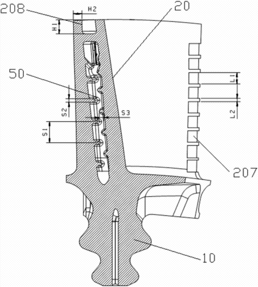
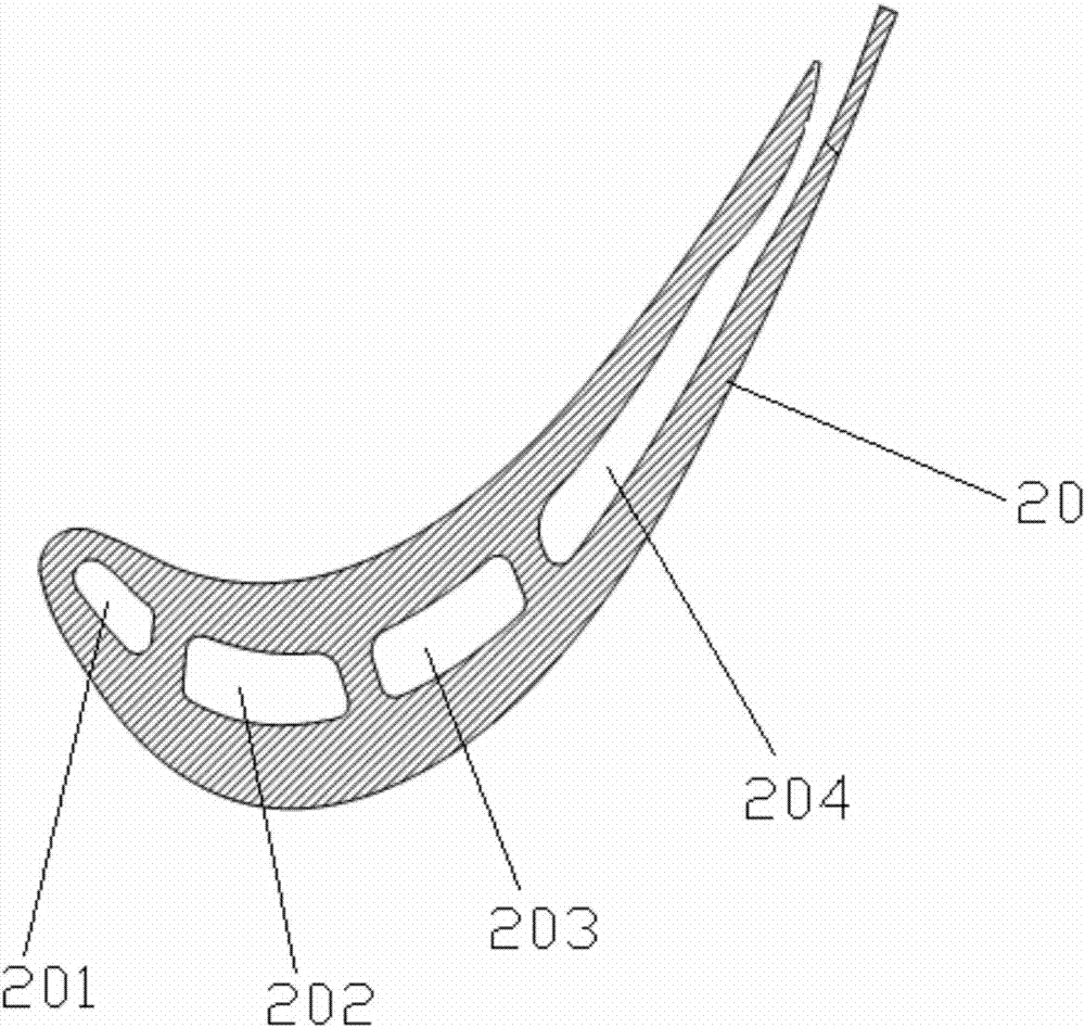
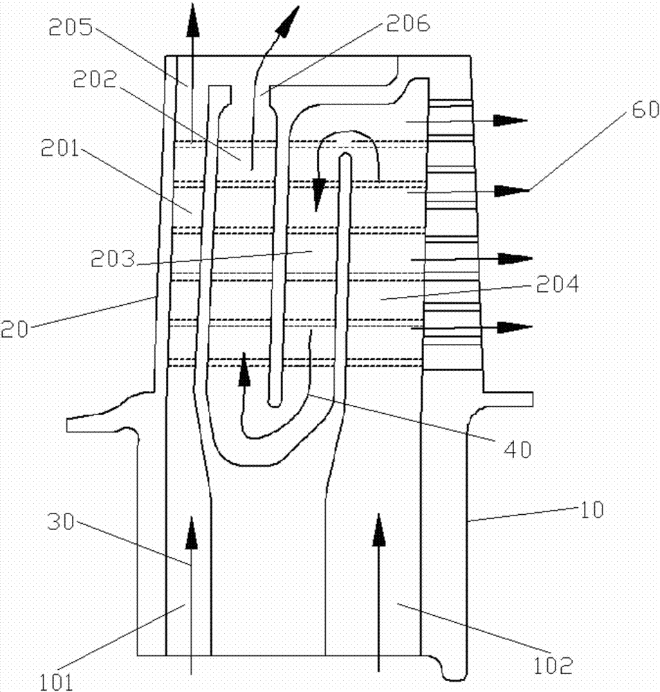
[0026] refer to Figure 1 to Figure 3 , the preferred embodiment of the present invention provides a turbine rotor cooling blade, including a tenon 10 and an airfoil 20 connected with the tenon 10; The first chamber 201, the first chamber 201 extends from the root of the blade toward the tip of the blade; the first cooling airflow 30 enters the first chamber 201 from the first air inlet 101 on the tenon 10, and flows from the tip of the blade The first exhaust port 205 of the blade is discharged to the outside; the airfoil 20 is also provided with a second chamber 202, a third chamber 203 and a fourth chamber 204 for the second cooling airflow 40 to pass through to cool the mid-chord region of the blade , the second chamber 202, the third chamber 2...


PUM


Abstract

The invention discloses a cooling blade of a turbine rotor. The cooling blade comprises a tenon and a blade body; the blade body is provided with an independent first cavity for first cooling airflow to pass through for cooling the front edge of the blade, and the first cavity extends from the blade root to the blade tip; the first cooling airflow enters the first cavity from a first air inlet in the tenon and is discharged from a first exhaust port in the blade tip; the blade body is further provided with a second cavity for second cooling airflow to pass through for cooling the middle chord area of the blade, a third cavity and a fourth cavity, the second cavity, the third cavity and the fourth cavity are sequentially distributed from the front edge of the blade to the tail edge of the blade and extend from the blade root to the blade tip, and the fourth cavity, the third cavity and the second cavity sequentially communicate with one another in an end-to-end mode; and the second cooling airflow entering the fourth cavity from a second air inlet enters the third cavity and the second cavity sequentially and finally is discharged from a second exhaust port in the blade tip.

Description

technical field [0001] The invention relates to the field of aero-engines, in particular to a turbine rotor cooling blade. Background technique [0002] At present, the cooling technologies that are widely used at home and abroad include radial channel convection cooling, impingement cooling, air film cooling, rough surface enhanced heat transfer, trailing edge slit cooling, etc. [0003] The radial direct-flow internal cooling channel of the blade is the simplest form of cooling. The cooling gas flows in the channel and absorbs heat through convective heat exchange to reduce the temperature of the blade body; air film cooling is achieved by spraying cold air from the nozzle on the wall surface of the blade. A cooling method that blocks the heating of the wall surface by the main gas flow. In addition, the gas film can also protect the working surface in harsh environments from corrosion; impingement cooling belongs to convective heat transfer, and there is a high The heat ...

Claims


Application Information

Patent Timeline
Patent Type & Authority Patents(China)
IPC IPC(8): F01D5/18
CPCF01D5/18F01D5/187
Inventor 常艳贺宜红孙瑞嘉郝旭生谢昌坦
Owner CHINA AVIATION POWER MACHINE INST
Why Eureka
Try Eureka