Anti-jitter circuit

An anti-jitter, circuit technology, applied in electrical components, pulse processing, pulse technology and other directions, can solve problems affecting narrow pulse filtering, increase filtering time constant, application limitations, etc., to eliminate rising edge jitter and eliminate falling edge. dithering effect

Active Publication Date: 2016-11-02
邳州市景鹏创业投资有限公司
View PDF2 Cites 5 Cited by
  • Summary
  • Abstract
  • Description
  • Claims
  • Application Information

AI Technical Summary

Problems solved by technology

When using the RS flip-flop, the key switch is required to have both a normally closed switch and a normally open switch, and its application is limited
When the RC filter circuit is used, when the jitter interference is continuous narrow pulse interference, the filter time constant needs to be increased to affect the rapid response capability of the circuit; or when there is continuous narrow pulse interference in the button circuit, the RC filter circuit has a DC memory effect. The previous narrow pulse will affect the filtering of the following narrow pulse

Method used


Image

  • Anti-jitter circuit
  • Anti-jitter circuit
  • Anti-jitter circuit

Examples


Embodiment Construction

[0020] The present invention will be further described below in conjunction with accompanying drawing.

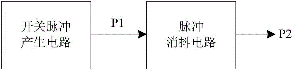
[0021] like figure 1 Shown is a structural block diagram of an embodiment of the anti-jitter circuit, including a switch pulse generation circuit and a pulse debounce circuit. The switching pulse generation circuit outputs the switching pulse P1 generated by the button or switch operation, and the switching pulse P1 is sent to the pulse debounce circuit for pulse debounce to obtain the output pulse P2.

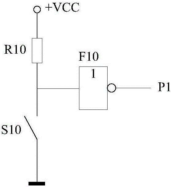
[0022] The switch pulse generating circuit is used for generating and outputting a switch pulse when a switch or key is operated. like figure 2 Shown is an embodiment of the switching pulse generating circuit, which is composed of a switch S10, a resistor R10, and a driving gate F10. The switching pulse P1 is output through the driving gate F10, which can improve the load carrying capacity of the switching pulse P1. When selecting the driving gate F10, you can choose t...


PUM


Abstract

Provided is an anti-jitter circuit which comprises a switching pulse generating circuit, a forward anti-interference circuit, a backward anti-interference circuit, and a data selector. An output pulse controls the data selector in order to switch an output signal of either the forward anti-interference circuit or the backward anti-interference circuit as the output pulse. The anti-jitter circuit may automatically filter out a positive narrow pulse during a negative wide pulse and a negative narrow pulse during a positive wide pulse, especially may filter out key or switch contact jitter narrow pulse interference signal. The maximum widths of the positive narrow pulse and the negative narrow pulse required to be filtered out can be regulated by changing a charge time constant and a discharge time constant, respectively. The anti-jitter circuit can be used in the fields where a circuit is required to reliably remove key or switch pulse jitter influence.

Description

technical field [0001] The invention relates to a mechanical button or switch pulse signal processing circuit, in particular to an anti-vibration circuit. Background technique [0002] In digital signal circuits, it is often required to output pulses when mechanical buttons or switches are pressed. When the mechanical key switch is pressed or released, the switch pulse will generate a jitter interference pulse due to the jitter of the contact. Using software to eliminate switch jitter needs to consume CPU working time, which greatly wastes system resources. When it is necessary to use a circuit to eliminate the influence of the jitter pulse of the key switch, the commonly used methods are RS flip-flop and RC filter circuit. When the RS trigger is used, the key switch is required to have a normally closed switch and a normally open switch at the same time, and its application is limited. When the RC filter circuit is used, when the jitter interference is continuous narrow ...

Claims


Application Information

Patent Timeline
Patent Type & Authority Applications(China)
IPC IPC(8): H03K5/1254
CPCH03K5/1254
Inventor 王兵凌云郭艳杰
Owner 邳州市景鹏创业投资有限公司
Why Eureka
Try Eureka