Method of writing pattern on media and data storage device

a technology of data storage device and pattern, which is applied in the direction of magnetic recording, digital recording, instruments, etc., can solve the problems of difficult to precisely control the rotation of the spm, and there is a significant amount of jitter, so as to reduce the effect of jitter in the rotation of the media and accurate timing

Inactive Publication Date: 2009-05-12
HITACHI GLOBAL STORAGE TECH NETHERLANDS BV
View PDF15 Cites 6 Cited by
  • Summary
  • Abstract
  • Description
  • Claims
  • Application Information

AI Technical Summary

Benefits of technology

[0014]Unlike the case of conventional SSW using a dedicated servo-writer, it is possible to use the intrinsic circuit of an HDD to self-write a servo pattern on a magnetic disk. Self-complete execution of self-writing of a servo pattern by the intrinsic circuit of an HDD makes a dedicated servo writer unnecessary, and this removes the requirement for a large investment to the equipment for servo write in the manufacturing.
[0032]In accordance with the invention, in self-writing a pattern on a rotating media, effect of jitters in the rotation of the media may be reduced and patterns may be written in more accurate timing.

Problems solved by technology

However, in the case where an ordinal HDD carries out the SSW by its own mechanism and circuit as described above, it is difficult to precisely control rotation of an SPM unlike the case of using a dedicated external servo writer, and there exists a significant amount of jitter in rotational speed (rotational jitter) of a magnetic disk.
This causes unequal pattern intervals in the written patterns on the magnetic disk using a certain fixed clock, and the patterns cannot be written on a same track at equal intervals or a difference in phase occurs between patterns of adjacent tracks.

Method used


Image

  • Method of writing pattern on media and data storage device
  • Method of writing pattern on media and data storage device
  • Method of writing pattern on media and data storage device

Examples


Embodiment Construction

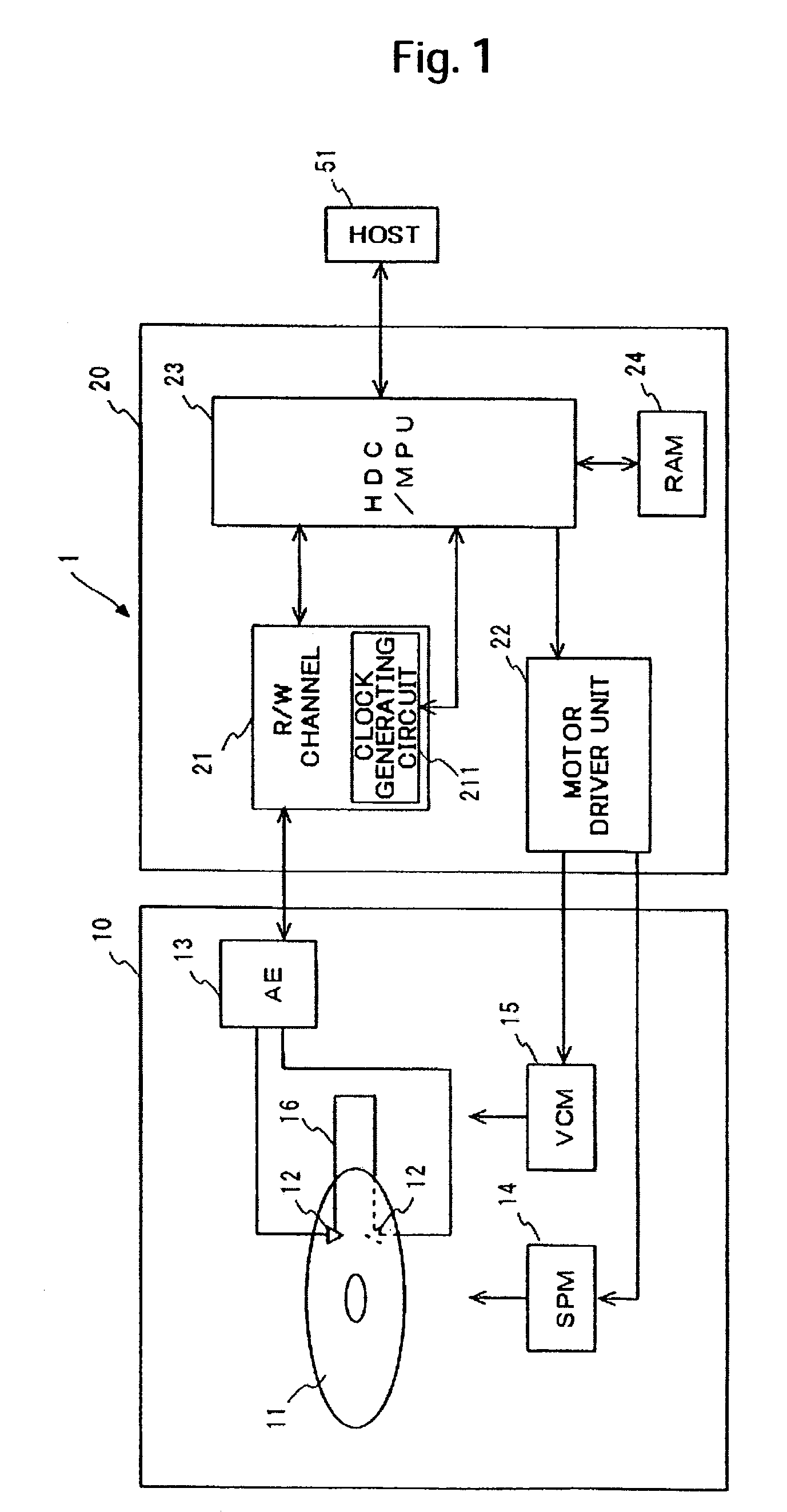
[0040]Specific embodiments of the invention will be described in detail hereinafter, with reference to the drawings. The following description and the drawings may be properly omitted or simplified for clarity of description. In the drawings, same elements are designated by the same reference numerals and signs and repeated description is omitted in order to simplify the description.

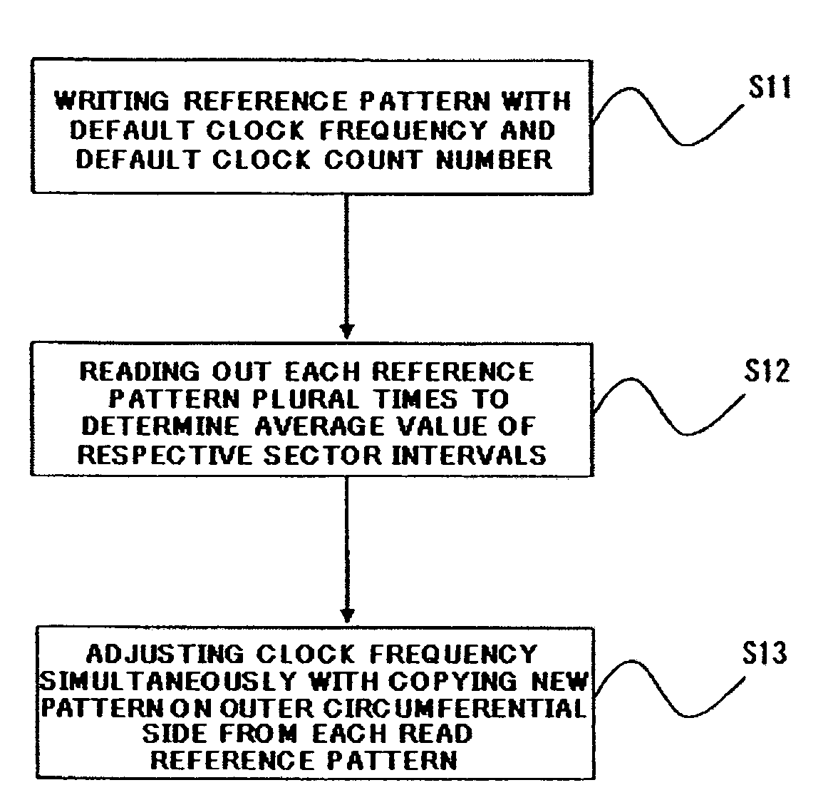
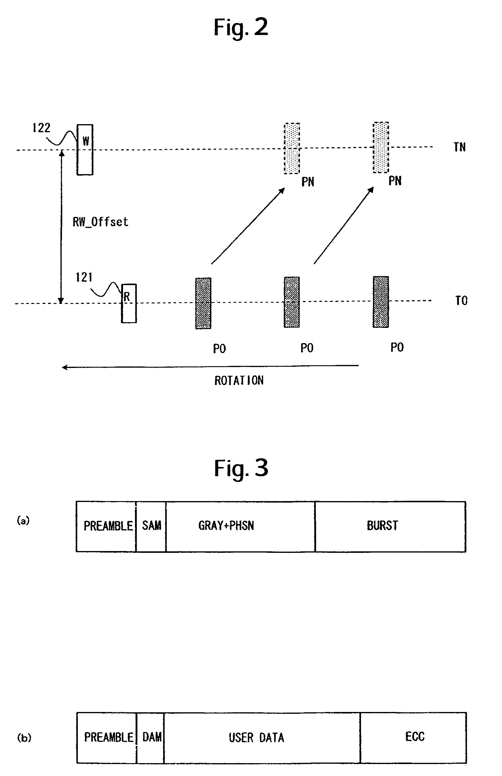
[0041]The embodiments are related to self-pattern-writing on a media in a data storage device, that is, a process of writing of a new pattern on the basis of self-written patterns on a media, particularly, control of timing for writing in self-pattern-writing. In the embodiments, a process of self-writing a servo pattern in a hard disk drive (HDD), which is an example of a data storage device, is explained to describe the example of the invention.

[0042]Self servo write (SSW) for writing a servo pattern by means of its own mechanism of an HDD has been known. In an HDD in a preferred embodiment, a function...


PUM

PropertyMeasurementUnit
read timeaaaaaaaaaa
timeaaaaaaaaaa
clock frequencyaaaaaaaaaa

Abstract

Embodiments of the invention reduce the effect of the rotational jitters to write a pattern in more accurate timing in self-writing a pattern on a magnetic disk. In an embodiment of the invention, respective patterns in N sectors are first written on an inner circumferential side track as reference patterns with a default clock frequency and a default clock number (a writing interval clock number between respective patterns). The respective reference patterns are then read out plural times for measuring intervals thereof to determine an average value of intervals between the respective sectors. Using the value, a target value is calculated in each sector, which is used in wiring new patterns on the outer circumferential side at even intervals. Then, the respective reference patterns on the inner circumferential side track are read out while the new patterns are written on the outer circumferential side. The respective outer circumferential side patterns are written with the modulated clock frequency after a delay time calculated for every sector has passed from the time when the reference patterns on the inner circumferential side track are detected.

Description

CROSS-REFERENCES TO RELATED APPLICATIONS[0001]This application claims priority from Japanese Patent Application No. JP2005-223332, filed Aug. 1, 2005, the entire disclosure of which is incorporated herein by reference.BACKGROUND OF THE INVENTION[0002]The invention is related to a method of writing a pattern on a media and a data storage device, particularly, control of timing in writing a pattern on a rotating media.[0003]A device using various kinds of medium such as an optical disk and a magnetic tape as a data storage device is known. Among such devices, a hard disk drive (HDD) is widely used as a storage device of a computer and is an essential device in a current computer system. Furthermore, the excellent characteristics of HDD have increased the area of the usage of the HDD not only in a computer system but also in a removable memory used in a moving picture image recording / playing device, a car navigation system, a cellular phone, a digital camera or the like.[0004]A magneti...

Claims


Application Information

Patent Timeline
Patent Type & Authority Patents(United States)
IPC IPC(8): G11B20/10G11B21/02
CPCG11B5/59633G11B5/59638
Inventor SAI, FUMINORITAKASAKI, KOHJISHOHDA, MASAHIROYANAGISAWA, HIROSHI
Owner HITACHI GLOBAL STORAGE TECH NETHERLANDS BV
Why Eureka
Try Eureka