
Electric motor with brake

A technology of electric motors and brakes, which is applied in the direction of motor generator control, electromechanical brake control, electric components, etc., to avoid cost increase and achieve the effect of braking force

Inactive Publication Date: 2016-11-02
MITSUBISHI ELECTRIC CORP
View PDF4 Cites 2 Cited by
  • Summary
  • Abstract
  • Description
  • Claims
  • Application Information

AI Technical Summary

Problems solved by technology

This brake is usually used as a holding brake, but there are cases where the holding brake is activated for braking purposes in an emergency or an emergency

Method used


Image

  • Electric motor with brake
  • Electric motor with brake
  • Electric motor with brake

Examples


Embodiment Construction

[0015] A motor with a brake according to an embodiment of the present invention will be described below with reference to the drawings. In addition, this invention is not limited to embodiment shown below.

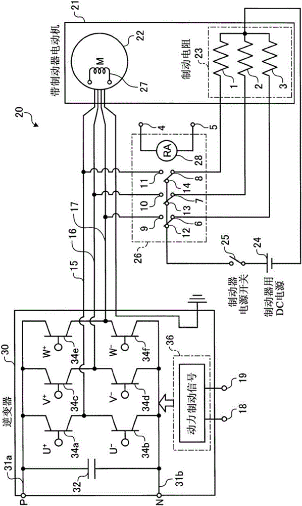
[0016] figure 1 The diagram showing the configuration of a motor system including the motor with brake according to the embodiment shows a configuration example in the case where the motor system is driven by an inverter. Such as figure 1 As shown, the motor system 20 according to the embodiment includes: a motor with brake 21 including a motor 22 and a braking resistor 23; a DC power supply 24 for the brake; a brake power switch 25; and a relay element 26. The motor system 20 is configured as , the motor 22 is driven by the inverter 30 .

[0017] The inverter 30 is a known circuit structure, such as figure 1 As shown in FIG. + ) and the switching element 34b (U - ) are connected in series, and three of these series circuits are connected in parallel to form a UVW ph...


PUM


Abstract

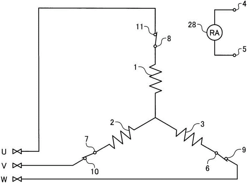
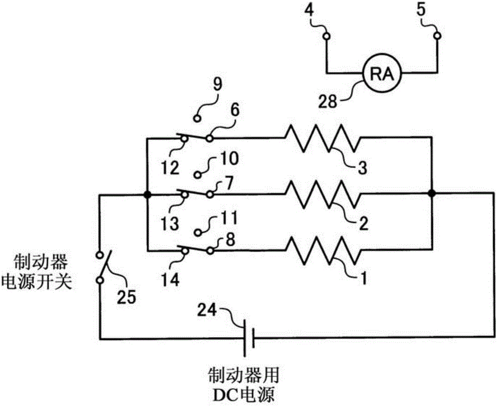
In an electric motor with brake having a holding brake function, a brake resistor (23) is equipped with three resistors (1, 2, 3). In a normal time, one end sides of the respective three resistors (1, 2, 3) are commonly connected to each other and the other end sides thereof are also commonly connected to each other, and the three resistors (1, 2, 3) are connected in parallel with a brake DC power supply (24). In an emergency time or an emergency stop, the one end sides of the respective three resistors (1, 2, 3) are commonly connected to each other to form a Y-connection, and the other ends that are not commonly connected are electrically connected to the output ends of a stator coil (27) of an electric motor (22) or to ends having the same potentials as those of said output ends.

Description

technical field [0001] The present invention relates to a motor with a brake. Background technique [0002] For example, a rotating electric motor such as a servo motor (hereinafter simply referred to as a "motor") is often provided with a brake function. This brake is usually used as a holding brake, but there are cases where the holding brake is operated for the purpose of braking in an emergency or an emergency. [0003] Here, as a typical structure of the holding brake, a lining that is fitted with the shaft of the motor is usually provided. In this structure, the holding brake operates by applying a braking force to the lining while maintaining the stopped state of the electric motor, and by utilizing the magnetic force generated by energizing the exciting coil when the electric motor is driven. Momentum, so that the braking force acting on the lining becomes zero, and the braking force is released. [0004] In addition, the brake device described in the following Pa...

Claims


Application Information

Patent Timeline
Patent Type & Authority Applications(China)
IPC IPC(8): H02P3/18
CPCH02K7/10H02P3/22H02K7/106H02P15/00
Inventor 森修一长谷川治之片江彻
Owner MITSUBISHI ELECTRIC CORP
Learn More